CTS 2333 (Unix/Linux
Networking) Lecture Notes
By Wayne Pollock
Lecture 1 — Course, Career
Overview
Welcome! Introduce course.
Discuss SA job titles (show booklet), salary (starting w/BS
degree: ~$60k), politics (soft skills). Discuss HCC major
(program codes), certificates, and degrees.
Discuss Project 1 (mention no LVM),
install Linux. Pass out Fedora DVDs (CDs available from DistroWatch.com). Discuss system
journal — Use wiki.
Have students use wiki to pick host
names and user IDs (need to be unique in class). Mention post install
tasks (on web).
Networking Career guidance
We call you a networking
professional but you may not be treated like a professional. Other titles
include network engineer and network administrator. There are
various levels: apprentice/novice (work under close supervision
on limited tasks including help desk), journeyman (not usually
called that), do a lot of diverse activities under loose directions from senior,
who will often plan, design, make policy, and help troubleshoot the really
tough ones. In a smaller company even inexperienced network professionals may
do many different tasks, including installing, configuration, monitoring, and
troubleshooting servers and workstations for many different platforms. You
will need to understand design issues (say to place a new server) and protocols
(to configure and troubleshoot), and to understand your users.
There are specializations
available: WAN, LAN, routing and switching, security (hot field right now),
voice/data networks, remote access and mobile computing, and in-depth knowledge
of specific vendor networking products from Microsoft, Novel, Unix/Linux,
Cisco, and others.
Never look in a newspaper
for ads, look on-line: HotJobs.com, Monster.com, Dice.com, ComputerJobs.com,
BrainBuzz.com, FloridaJobLink.com, ITcareers.com, ...
Soft Skills (See Soft Skills web resource)
Customer relations (listen,
respond positively by guiding them away from bad ideas. Must have good oral
and written skills. Must be dependable, able to work well in a team.
Leadership is important for non-entry level positions.
Understand business/management
procedures, politics, and concerns. (ITIL).
Get networked: join a
professional society or two: Network Professional Association www.npa.org, ACM
acm.org, IEEE/CS computer.org, etc. Go to meetings (make contacts or network).
(Cheap student chapters, many benefits.)
Get certified:
Unix/Linux (LPI, Novell, Sun, ...), Cisco, CompTIA, and MS.
Basic Network Utilities to Know
There are many command line
tools that are commonly used to access resources across a network. Additional
configuration and troubleshooting tools are discussed later. A few you should
know about include:
ftp File Transfer
Protocol/Program. One of the earliest tools, it has a strange protocol
(requires a call-back on a different port from the server) and has many
security problems. Only anonymous FTP should be used anymore (username is
anonymous, password is a valid email address).
tftp Trivial FTP. The
only common use it to load configuration data into switches, routers, and other
network devices. Modern ones should support a more secure protocol.
telnet (also rlogin and rsh) Old, insecure protocol for remote login sessions.
(Use control-] to suspend session and bring up telnet>
prompt.)
ssh (Secure SHell)
Used to create a secure tunnel over which remote login sessions can occur.
However the tunnel can be used for other protocols such as scp and sftp, which
are used today instead of ftp. (FTPS is also used, but that doesn’t use ssh.)
wget (and curl) A zillion options, can
fetch any file for any FTP or HTTP[S] URL. Using wget -S --spider URL won’t fetch the document but shows the response
headers, useful for troubleshooting. curl
supports more protocols include LDAP, Telnet, etc.
nc (Called netcat on some systems.) Use like
cat only across a network.
links A (console) mode web
browser. Renders HTML pages as well as possible using only text. Can be used
to extract text from web pages.
Lecture
2 — Networking Standards and Standards Organizations
Networking
Standards
There are thousands of standards
relating to networking! These are far too many to publish in any one reference
book, and in any case the standards are changing and growing all the time. So
you must locate the standards when you have networking questions! These are
generally available on-line but some organizations sell copies of standards,
for up to thousands of dollars a copy. (PDFs of these can often be purchased
for around $20.)
A system admin must be aware
of where to locate networking information, which organizations are responsible
for networking standards and services, what legal and administrative
requirements must be met by your network and servers.
RFCs
There are thousands of Requests
for Comments. Despite the name, these are the official Internet
standards. Not all RFCs pertain to Internet protocols and not all networking
standards are published as RFCs (IEEE, ISO, ITU, W3C, and proprietary standards
generally are not). However most of what a SA or NA (Network Administrator)
needs to know is published as RFCs.
The Requests for Comments (RFC)
document series is a set of technical and organizational notes about the
Internet (originally the ARPANET), beginning in 1969. Memos in the RFC series
discuss many aspects of computer networking, including protocols, procedures,
programs, and concepts, as well as meeting notes, opinions, and sometimes
humor. RFCs are generally ASCII text documents. The most recent ones can be
found at tools.ietf.org/html.
You can use a nicer search form at www.rfc-editor.org/rfcsearch.html.
The official specification documents of
the Internet Protocol suite that are defined by the Internet Engineering Task
Force (IETF) and the Internet Engineering Steering Group (IESG ) are recorded
and published as standards track RFCs. As a result, the RFC
publication process plays an important role in the Internet standards process.
RFCs must first be published as Internet
Drafts. RFC 2026 describes The Internet Standards Process.
The RFC Editor is the
publisher of the RFCs and is responsible for the final editorial review of the
documents. The RFC Editor also maintains a master file of RFCs called the “RFC
Index”, which can be searched online. For nearly 30 years, the RFC
Editor was the legendary Jon Postel; today the RFC Editor is a small
group funded by the Internet Society.
Text file format (must use CRLF): See rfc-editor.org/EOLstory.txt.
Each RFC has a category
or status designation. The possible categories are:
·
PROPOSED STANDARD, DRAFT STANDARD, STANDARD
These are standards-track documents, official specifications of the
Internet protocol suite defined by the Internet Engineering Task Force (IETF)
and its steering group the IESG.
An RFC starts life as an Internet Draft. The Internet Draft is proposed
to the IETF, whereupon voting and modification occurs until it either becomes
obsolete due to lack of interest or is accepted by the IESG, whereupon it is
assigned an RFC number and published as a proposed standard RFC. If it
doesn’t become obsolete the RFC becomes a draft standard and eventually an
Internet standard, and is assigned a STD number (in addition to its RFC
number). The process by which an RFC is produced is described in detail in RFC
2026.
·
BEST CURRENT PRACTICE
These are official guidelines and recommendations, but not standards, from the
IETF. These RFCs are also assigned a BCP number.
·
INFORMATIONAL, EXPERIMENTAL
These non-standards documents may originate in the IETF or may be
independent submissions (e.g., Cisco, Novell, Microsoft, etc., may submit these
RFCs).
·
HISTORIC
These are former standards that have been actively deprecated.
Each RFC is numbered. For instance,
RFC 791 documents the IP protocol. Although most RFCs are generally are quite
readable, others are nearly impossible to read (written in “standardese”).
RFCs never change or get
updated (except for minor typo corrections). This avoids any hassle with
incompatible versions of standards. When necessary a new RFC is created that obsoletes
the original one. However, the RFC Editor does maintain errata for RFCs, and
RFCs obsoleted by a newer RFC sometimes list the new RFC number at the top (not
always). (Show RFC-822->2822->5322.)
STD and BCP numbers
also never change. However, when a STD or BCP is updated, it simply refers to
a newer RFC (or set of RFCs). For example, STD1 is currently defined by
RFC5000 since 2008. Before that, STD1 was RFC3700 (since 2004), and before
that, RFC3600, and so on. (I think the first version of STD 1 was defined by
RFC1038, in 1988.)
Further information on the RFC
documents and the IETF, the body that produces them, can be had at www.rfc-editor.org (demo),
the home of the RFC Editor. RFCs can be found in several other repositories
(mirrors), including www.ietf.org/rfc/rfc#.txt
, rfc.net , and
elsewhere. Some of these have converted the text documents to HTML.
Standards
Bodies and Organizations
An alphabet soup of groups oversee the
Internet: IANA, ICANN, IETF, IAB, ISOC, IESG, and the W3C. The Internet
Society (ISOC) charters the Internet Architecture Board
(IAB), the Internet Engineering Task Force (IETF), the Internet
Engineering Steering Group (IESG), and the Internet Assigned
Numbers Authority (IANA). Other groups also are responsible for
networking standards: ISO, IEEE, ITU, OASIS, and no doubt others I’ve
forgotten!
The IANA is the clearinghouse
and distribution point for network parameters (such as IP addresses, protocol
and port numbers, AS numbers, and TLDs). The actual definition of these is up
to the IETF, organized into a number of different working groups. These groups
are under the oversight of the IESG. The IESG in turn is under the oversight
of the IAB, which also adjudicates any disputes between these groups.
The IAB is chartered both as a
committee of the Internet Engineering Task Force (IETF) and as an advisory body
of the Internet Society (ISOC). Its responsibilities include architectural
oversight of IETF activities, Internet Standards Process oversight and appeal,
and the appointment of the RFC Editor.
The IAB was also responsible for the
management of the IETF protocol parameter registries. Previously, there was no
commercial involvement and all management decisions were up to the
IETF/IAB/ISOC. With the growth and worldwide acceptance of the importance of
the Internet, many countries and companies felt that the non-profit management
of the Internet by the ISOC, which had no legal standing by any country, was no
longer appropriate.
The IETF used a single company, Network
Solutions, Inc. as the sole registrar for DNS domain names. Many
companies wanted to make a profit from selling DNS services and Network
Solutions had a monopoly. Additionally most DNS root servers (like
Network Solutions) are operated by U.S. corporations, giving the U.S.
government a lot of say about what TLDs would be allowed.
Parts of Internet management (domain
name services) have become commercialized. To oversee the commercial DNS
service providers (“DNS registrars”), a number of countries then
built the Internet Corporation For Assigned Names and Numbers
(ICANN), which “usurps” much (but not all) of the management tasks from the
IETF.
The ICANN accredits companies and
organizations for domain name registration. They appoint an authoritative
registrar for each TLD. This registrar maintains the database for that
domain, including tracking which registrar has registered which domain names.
For example, VeriSign (which bought out Network Solutions) is the authoritative
registrar for .com and many
other TLDs. (See www.internic.net/regist.html
or ICANN’s website to find a list of DNS registrars for some TLD such as “.com”, and then visit those organizations’
websites for info.) This database is called the whois database.
It is distributed; each registrar maintains the records for the domains it has
registered.
ICANN has its own committees, or as
they call them, support organizations (or SOs). There is the address
SO, aso.icann.org,
and the generic and country code TLD SOs, gnso.icann.org and ccnso.icann.org.
These SOs advise ICANN much like the working groups supported the IETF.
Currently, ICANN still uses the IANA to
manage all the assignments.
ICANN has no oversight from the IAB or
IESG, they only respond to the member countries (which never agree on anything,
so essentially ICANN has no oversight). However, the ISOC/IETF does get
to appoint two members to the ICANN board. This chaos, along with a lack of
coordination with the ISOC, has so far resulted in ICANN being largely
ineffectual, and a breakdown of Internet regulation.
The newness of ICANN
caused it to have an agreement (the “JPA”) with the U.S. Gov. to oversee ICANN
for its first few years. ICANN’s memorandum of understanding with the U.S.
Department of Commerce ended in 2006 but was at that time renewed, and ended in
Sept. 2009. The agreement gave the U.S. full control and veto over ICANN
rules. The JPA wasn’t renewed when it expired. However, the U.S. maintains a
permanent seat on the ICANN’s accountability panel.
Even after the JPA
expired, ICANN still has a separate contract to have the U.S. operate the IANA
(Internet Assigned Numbers Authority). So they would not be completely
free of U.S. oversight. This agreement expires in 2011, unless renewed.
Note the JPA expired
40 years to the day (10/1/1969) when the second computer was connected to
ARPAnet, the first network.
For example, today nearly any registrar
can be accredited to manage any TLD, and the rules for who can get a domain
name in various TLDs are largely ignored. ICANN has authorized many new TLDs,
but a (small) number of registrars have ignored them and created any TLD a
customer wishes. Since some DNS servers recognize only some TLDs, this causes
big problems for everyone.
Note that ICANN still uses the IANA
as a clearinghouse and distribution point for the TLDs. The IANA still
maintains the list of root servers.
Originally of course, all the DNS root
servers were operated by the U.S. government; IANA doesn’t set policy. After
ARPA and NSF stopped funding the Internet, in 1997 the NTIA (National
Telecommunications and Information Administration), an agency of the U.S.
Dept. of Commerce, took over. They paid for and managed the DNS root servers,
keeping control of the passwords needed to update that, and were the only body
that officially could instruct the IANA to add new (or remove) TLDs.
Even after ICANN was formed, the NTIA
retained control. In 2005, the U.S. announced they would not relinquish
control of the DNS root servers to the international community (probably some offshoot
organization of ICANN).
But in 3/2014, the U.S. DoC announced
it would turn over control to ICANN. (This might be a reaction to the Snowden
revealations.) Thereafter, ICANN would have the final say about DNS policy and
instruct the IANA. The DoC actually announced they want a new group formed
for oversite of ICANN first.
The U.S. announced it will transfer
governance of the Internet domain name system (DNS) to a multi-stakeholder
entity on Oct. 1, 2016.
National
Telecommunications and Information Administration (NTIA) administrator Lawrence
E. Strickling on Tuesday said his agency notified the Internet Corporation for
Assigned Names and Numbers (ICANN) that “barring any significant impediment,”
NTIA plans to permit its Internet Assigned Numbers Authority (IANA) contract
with ICANN to expire as scheduled.
ICANN announced in August 2016 that the
nonprofit public benefit corporation Public Technical Identifiers had
been incorporated in California to run IANA’s functions after the transition
was complete, which includes responsibility for the coordination of the DNS
root, Internet Protocol (IP) addressing, and other IP resources.
Actually, this is an
over-simplification of the real history. On Sept. 2 1969, SRI (Stanford Research Institute,
in Menlo Park, CA., and now an independent research institute, SRI Intl.)
attached the second computer to ARPAnet. UCLA was the first node. The
switches were built to ARPA’s specs by BBN. Charley Kline sent the first two
characters, “LO”, trying to type “LOGIN”. But the SRI computer crashed at the
“G”. Later it was claimed he was trying to send “Lo and Behold!”; the restored
lab at Boelter Hall UCLA, now a museum, has that phrase spelled in ASCII, in a
tile mosaic.
SRI was in charge of
coordinating the users and researches using ARPAnet, and they established the Network
Information Center, or SRI-NIC for that purpose. When ARPAnet was renamed
to the DDN (defense department network), SRI-NIC became known as
DDN-NIC. This NIC kept all the documents (now called RFCs) as well as who was
assigned which network numbers (a primitive version of the WHOIS database,
originally kept on 3x5 inch index cards).
The NIC also managed
domain names. Owners of new hosts sent email to HOSTSMASTER@SRI-NIC.ARPA
to request an address. A file named HOSTS.TXT
was distributed by the NIC and manually installed on each host on the network
to provide a mapping between these names and their corresponding network
address. Once the DNS system was created, DDN-NIC also performed DNS root
nameserver administration.
In 1990, the IAB
proposed changes to the NIC/IANA arrangement. The Defense Information Systems
Agency (DISA) awarded the administration and maintenance of DDN-NIC, which had
been managed by SRI since 1972, to Government Systems, Inc. They in turn subcontracted
it to the small private-sector firm Network Solutions, Inc.
Two years after that,
the DoD decided not to continue funding the Internet, except for the management
of the .mil TLD. In 1993, the NSF
took over funding the Internet, and created the Internet Network Information
Center (InterNIC) to take over for DDN-NIC. They originally awarded the
contract to three organizations, but after a couple of years, Network Solutions
took over all the duties of running the InterNIC.
So officially, SRI
managed the Internet from its inception until the early-1990s. In 1998, both
IANA and InterNIC were placed under the control of ICANN, which then then privatized
the DNS system.
The U.S. kept a
controlling share of ICANN votes, and a veto, for the next ten years. ICANN
then began selling TLDs (names in the .xxx
TLD went on-sale in 2012) and registration services to almost any company with
sufficient cash. The DNS system may never recover.
The IEEE is the organization
responsible for popular Layer 2 standards: Ethernet, Wi-Fi, Li-Fi, etc. They
control MAC addressing.
The ITU is the descendant of
CCITT and controls telephony standards and radio frequency allocations, amongst
other tasks. The ITU is charted by the United Nations to coordinate global telecom
networks and services.
The ISO is responsible for a
variety of networking related standards, including some Layer 1 (physical
layer) standards, country codes (the two and three letter abbreviations used in
TLDs), etc.
The ISO is most famous for their OSI
seven layer model of networking. Note however the Internet is based on the
US-DoD four layer model of networking. (This is based on the original Arpanet
Reference Model (ARM), and some count the physical layer as a fifth layer.)
ISO is the International
Organization for Standardization. Because it would have different
acronyms in different languages (“IOS” in English, “OIN” in French for Organisation
Internationale de Normalisation), its founders decided to give it also a
short, all-purpose name. They chose “ISO”, derived from the Greek isos,
meaning “equal”. Whatever the country, whatever the language, the short form
of the organization’s name is always ISO.
The IANA is responsible for
protocol numbers, port numbers, and AS (Autonomous System, a.k.a. routing
domains) numbers for the IETF), maintaining the DNS root servers “hints”
file, and maintaining the official TLD DNS lists (for ICANN). You can find
anything they maintain from iana.org/protocols, such as IP
address assignments and a lot of reference information.
The World-Wide Web Consortium (W3C)
maintains many standards and protocols relating to Internet use. Examples
include HTML, CSS, SOAP, P3P, and many others.
OASIS (www.oasis-open.org) mainly deals with
e-business/e-commerce standards, such as UDDI (an XML Web services directory
lookup protocol), DocBook, OpenDocument (document standards), and WSDM-MUWS
(another web services protocol). Due to their restrictive licensing policies
some people don’t consider OASIS standards to be “open” and avoid using them.
Finally note that the presence of a
standard doesn’t mean everyone will use it! The advantage to using “open”
standards (where the specifications are widely available, and there is no
licensing fees or other restrictions on use) made the Internet possible.
SI Prefixes [Also discussed in Admin I]
All IT professionals should
know standard international (SI) units and prefixes. See wikipedia.org/wiki/International_System_of_Units
and physics.nist.gov/cuu/Units/prefixes.html.
kilo (1000 or 1024), mega, and giga.
For wavelengths and time you also should know: milli
(thousandth), micro (millionth), nano (billionth),
and pico (trillionth). Examples: KHz for kilohertz, msec or ms
for milliseconds, us or μs (Greek let mu + ‘s’) for microseconds, mb =
megabits, mbs = megabits per second. (Usually ‘b’ indicates bits and ‘B’
indicates bytes, but not always.) Technically SI units are multiples of 1,000
only. Rarely used are prefixes kibi, mibi, and gibi, for
multiples of 1,024.
France refuses to use
“bytes” but uses “octets”, so when we use kB/KB, mB/MB, and gB/GB they use
kO/KO, mO/MO, and gO/GO. (And sometimes kO, mO, and Go as well.)
Lecture
3 — Networking Concepts (part I)
What is a
network? Computers (a.k.a. hosts) able to share information and
resources. Physically this can be done via a cable (discuss crossover)
between the serial ports of two computers. (A computer attached to a network
is called a host. Any device attached to a network (a host, router,
switch, printer, ...) is called a node.
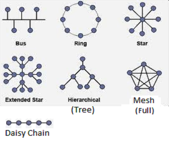
Qu: What is needed physically? Media
such as a cable between each pair of computers (called a mesh), or in a ring,
or in a bus, or in a star. What if you want to share with many
hosts (DTEC 4th floor has ~400 computers)? Connecting every computer to every
other with a cable takes a lot of serial ports and cables! (Known as a mesh
network.) More common approach is to have a single cable (a.k.a. trunk)
or hub (or switch) that all computers on the network share (known
as a bus network). Then each computer needs a unique address so
when one computer sends data to another, the intended recipient knows the data
was meant for it. The different network topologies are: mesh, partial mesh,
bus, star, ring.
Computer cables can be tricky to work with. They don’t work if
too long, and they work poorly if kinked, if not terminated correctly, or if
improperly grounded. When attaching a connector to the end of a cable, if you
straighten out 0.5in at the end more than you should, the 100Mb/sec cable will
only support about 30Mb/sec! Fiber optic cables can be trickier to work with.
Besides being more delicate then commonly supposed, standard
cables have safety issues. Such cables are clad in PVC, a strong, durable,
flexible, and cheap insulator. But in a fire the cables can get hot, and then
they give off deadly chlorine gas! In air spaces where people might be, you
need to use more expensive (but safer) plenum cable. There are
various building and safety codes to consider as well.
Fiber optic cables also have some safety issues: small glass
shards can get into your skin or eyes, and the invisible light coming from the
end of a fiber can permanently damage your eye in an instant.
In the end, you should consider using a licensed cable installer
(or get trained yourself).
In addition to media, you need some
hardware to connect the host to the media. This is called a NIC
(Network Interface Card). In Linux these have names such as “eth#”, where “#”=0,1,2,..., or
they are named for the bus and position (e.g., “p7p1”).
In Solaris, they have strange names, such as “elx#”
depending on the manufacturer/chipset of the NIC, but many modern NICs are
simply known as “hme#”.
Your operating system needs the correct
driver software to allow applications to send messages to the NIC. Then some
application can send a message to another host by invoking the proper API
function. The data will be passed to the NIC and then sent on its way.
Addressing
Qu: (point to network diagram) If this
host wants to send a message to that host, how does it do that? Ans:
each computer needs a unique address so when one computer sends
data to another, the intended recipient knows the data was meant for it. The
other computers on the network are supposed to ignore the message. In the
early days the administrator you manually set each NIC with a unique number
between 1 and 255. Today NICs come configured with an address already, known
as the MAC Address (and BIA, data-link address, ...).
Protocols
A cable alone is not sufficient to
permit computers to share resources. Each node must know there is another on
the other end of the cable. Each must be able to talk to the other. What
happens if both send at same time? (Ans: collision.) What should
happen if neither host sends anything for a long time? Agreed upon protocols
(rules of communication) and standards (examples: type of cable, what
each wire will be used for, how many volts, ...) are needed to communicate.
Some software must be listing to the
port that implements the agreed protocols. (A set of protocols that work
together is referred to as a protocol stack.) Example: file
transfer.
A network then is two or more
computers physically connected and communicating using agreed upon protocols. Ethernet
and TCP/IP are very commonly used sets of protocols. Other
protocols: (LAN) IPX/SPX, SMB, (WAN) SLIP, HDLC, PPP, UUCP. A network may
be small (one geographical location) or may cover the globe. Different
technologies are used in each case. For a local area network (LAN)
Ethernet is almost always used, which broadcasts the transmitted
data so every station sees them. (Wireless technology, often called Wi-Fi,
is also used for LANs.)
What if computers are far apart? LAN
technology won’t work! WANs (wide area networks) often use PPP
protocols. WANs usually connect LANs together, not individual computers,
through slower, error-prone serial links (point-to-point). (Draw
picture of packet hopping from LAN to LAN.) The different LANs composing a WAN
may use different protocols and technology. The LANs are often connected using
networking hardware called routers. Communications within a single
network are known as intranet, and between networks as internet.
“The” Internet is thus a WAN, connecting many company and
organization’s LANs together.
The WAN connecting
different sites is often leased from an ISP or telco. HCC for example uses
Level 3 Communications to connect the different campus (and the Lakeland backup
facility) to the data center in Ybor.
For host A to send data to host B,
host A must build a packet (a chunk of data) containing the data
plus a packet header which contains the destination address and
other information (e.g., packet length, type of data, ...). To transmit data
from one host/node to another, the application invokes API function, passing it
the address of the recipient and the data to send. API function builds the packet
from this info and sends the packet to the NIC. The NIC sends out the packet
onto the media, one bit at a time, according to the network protocol.
If the data is very large, the API
function will split it into several packets, which get reassembled at the
destination. (Example: FTP a large file; Ethernet max packet size is 1522
bytes including the header.)
Mostly, NICs will examine only
enough of the packet to see if it was intended for them or not. If not
they stop looking at it. The destination NIC will read in the whole packet,
compute a checksum, and compare it with the checksum at the end of the packet.
If they don’t match, the packet is corrupted and must be sent again.
The various protocols and their
associated configuration (along with other networking hardware such as routers
and switches) will be discussed in more detail later in this course. As a
system administrator, you will need to know the choices for networking
available to you, and how to configure your systems for various network design
choices. You will need to be able to build and configure simple, standard
networking, and to be able to communicate effectively with a network administrator.
Commonly
Provided Network Services
File/Application
- allows files and disk space to be shared.
Database –
server based database storage, retrieval, format, and security (LDAP)
Print - share
printers across a network. (IPP)
VOIP - Not
all networks carry TCP/IP data only. Voice and other data networks are also
common.
Remote Access
- (communications service) Allows remote users to communicate
with network hosts (typically just the servers), or enables communications from
the hosts on the network to remote hosts and networks (this is sometimes
considered an Internet service). Often this is done with a modem over an
ordinary phone line (or cable TV line). Microsoft uses the term RAS for
Remote Access Server, Novell uses NAS for Network Access Server.
Remote users must identify
themselves to the network before access is granted; this is known as logon
or logging in.
Commonly used remote access
client software (such as HyperTerm) uses protocols such as PPP, SSH, telnet,
and many others. (VPN, rsh: remote execution, PC Anywhere, Remote
Authentication Dial-In User Service (RADIUS), Terminal Access Controller,
Access Control System (TACACS+).)
Mail - Allows
the storage and transfer (forwarding) of email. Two popular mail
servers are Microsoft Exchange mail server, and Unix sendmail server.
Internet -
Allows your organization to use (or provide) some services from (to) servers
(users) on another network, connected by the Internet. Examples include file
transfer (FTP), world wide web (WWW or simple the web, HTTP), addressing
schemes and services, remote access to hosts on other networks, name services
(DNS), and more.
Naming - A
naming service provides a way to lookup addresses (and other data) using an
easy to remember name. The most common naming service is DNS.
Security -
firewalls, authentication, encryption, etc.
Management - This
includes many services such as network traffic monitoring (sniffing/snooping)
and control, load balancing, hardware monitoring (and automatic fault alerting,
e.g., signal a pager), fault isolation and diagnosis, asset management (i.e.,
hardware and software inventories), software license tracking, security audits
(and accounting), software updates (e.g., distribution of new software,
patches, configuration, and deletion of old software), address management
(DHCP), and backup and restore across a network.
Categorizing
Networks by type, size, ...
Networks can be characterized in many
ways, such as by size: Networks can be small (LANs) or
cover large distances (WANs). (MANs, CANs, PANs, and
IPNs: Metropolitan, Campus, Personal, and InterplaNETary.)
Networks may be either circuit
switched or packet switched.
Circuit switching
is how the old analog phone system
worked (start at 2-minute mark): As you dialed a digit of a phone
number, the local exchange had a rotary switch that would rotate around that
many contacts, then make an electrical connection. The next digit went to the
next rotary switch, and so on, until an electical circuit was established
between your phone and their phone.
Until you hang up the
phone, the wires involved in your circuit are used exclusively for that call.
There are only so many wires stretched between cities, and on Monday mornings, the
phone company can run out!
Packet switching
works without reserving any of the wires (so no circuit). The data to be sent
is digitized (if it wasn’t digital already) and split into small chunks called packets.
A “header” is added to the packet that contains, among other things, the
destination address for the packet. Each packet is sent out a NIC
independently, and travel over each wire between the sender and the destination
one hop at a time. The wire is not reserved for the duration of the session,
so it can be shared between many users.
Today most networks are packet
switched. These in turn are classified as either connection-oriented
or datagram (connectionless). (Web, FTP vs. DNS, NTP)
Packet switched networks can simulate circuits. This is known as virtual
circuit. (ATM networks use this.)
Networks can be connected in a variety
of ways. This is known as the physical topology of the network.
For example connecting all the computers in a LAN in a ring so that every host
connects with two other hosts, is called a token ring network
(Ex: ATM). Such rings can be connected together with special gateway
(connects two or more networks) hosts that are connected to two or more rings.
Other topologies include star, cell, and bus.
Another way to classify nets is peer-to-peer
vs. client-server.
Initially, most companies made
proprietary networking equipment that used proprietary protocols. Cisco became
huge by selling multi-protocol routers, ending vendor lock-in (except you were
then locked-into Cisco). Today Cisco remains the dominant networking
equipment supplier in the world. But there are others, such as Juniper and Garrettcom
(makes rugged network equipment for industrial settings).
Internet
Brief History [From: “BGP” by Iljitsch van Beijnum, (C)2002 O’Reilly]
The Internet started life as ARPANET
in 1969, funded by the US DoD. This was based in large part on revolutionary
work by Paul Baran at RAND corp., in 1960. His work included packet switching
and adaptive routing, amongst other ideas. Cold war fears required a robust
network that could work even if parts were knocked out. However, no such
network was built until years later.
ARPA (now called DARPA) needed a better
way to allow researchers to share results (and computing resources). It was
thought that researchers would use access to powerful computer centers to use
their special facilities, but the most common use was personal communications
(chatting and email, Netnews/Usenet), to share research.
The ARPANET initially connected just
four “nodes”, located at UCLA, the Stanford Research Institute, UC Santa
Barbara, and the University of Utah. By the end of 1971, there were fifteen
nodes. This network was primarily designed by Vinton “Vint” Cerf and Bob Kahn,
based on the earlier work of Paul Baran.
Initially these centers were reluctant
to connect to a network, but the ARPAnet design used separate mini-computers to
off-load all network functions. These were called IMPs (Interface
Message Processors), built by the engineering firm Bolt Beranek
and Newman (BBN). A site only needed a direct connection to the local
IMP. IMPs used the network control protocol (NCP) to communicate.
Later NCP was split into IP and TCP (and UDP).
Once ARPAnet was deemed a success,
other sites wanted connections. However, only a few sites were ever connected
directly to ARPAnet, the original Internet (the backbone of the
Internet).
To accommodate the others, NSFNET
was created and maintained by the NSF from the late 1980s until 1995. NSFNET
connected five supercomputer locations around the U.S. Note no commercial use
of the Internet was allowed on either network. (No ads!)
Internet
Exchanges
At that point, there were two separate
networks. To have traffic (data) to pass from one network to another requires
an Internet Exchange Point (IX or EP are common acronyms). The first
were built by the DoD; two 10-Mbps Ethernet switches, FIX-East and FIX-West.
Each IX connects traffic between cooperating networks. Other networks were
created too (e.g., Bitnet), and other IXes.
At an Internet
Exchange, the networks of Internet Service Providers, telecommunications
carriers, content providers, website hosting providers, and others, meet to
exchange IP traffic with one another. This exchanging of regional, national,
and/or international IP traffic is generally known as “peering”.
In general, parties
peer at an Internet exchange in order to decrease network costs, to improve network
performance, and to make their network more redundant. Accessing many networks
directly at the exchange (that otherwise would have taken several network
“hops” through other parties), improves network performance. Having many
routes at an exchange through which traffic can be sent, increases redundancy.
As of 2014, there are
about 460 Internet exchanges operating worldwide. (See this list of Euro
IX Peering arrangements.)
In 1995, NSFNET was de-commissioned to
allow commercial networks to grow. But to ensure connectivity the NSF awarded
contracts for four IXs called network access points (NAPs):
Pacific Bell NAP in San Jose, Ameritech NAP in Chicago, Sprint NAP in NJ, and
MAE East run by MCI WorldCom in VA (which was already operating an IX). (MAE =
Metropolitan Area Exchange. FIX=Federal IX, CIX=Commercial IX,
pronounced “kicks”.) After these six EPs, other networks and EPs were build
commercially.
Today, the Internet connects about
100,000 networks and millions of hosts (and 100s of millions of users). The
backbone is provided by many company networks (such as Sprint) who sell the
connections to ISPs, who sell connections to us. These major
network operators connect their networks at various IXs around the world, such
as PAIX (SwitchAndData.com), now Equinix. (Show IX
list at PCH.net.) Today many cities have IXs (MAEs) that are
run by either by a commercial company who sells access and other services, or
by a cooperative of those who use it (and pay for it).
An ISP needs office space plus a
connection to an IX (usually a cable run by a local Telco), plus peering
(where roughly equal-sized ISPs in the same geographic region transfer each
other’s data for free) and transit (where you pay for it)
agreements with the other network operators. To participate, you will need a
block of IP addresses (from ARIN, however many IXs will allocate addresses from
a block they use to aggregate routes for that region) and an ASN (Autonomous
System Number). IXs usually offer various services, such as co-location
of your router and theirs. (See www.peeringdb.com for
details on IXes and ISPs.)
There appear to be
two public IXes in Tampa: TampaIX (at the Franklin Exchange, 655 N Franklin
Street) and IXTampa (at eSolutions, 400 North Tampa Street). See this
list of IXes, maintained by Euro-IX.
Several groups oversee the Internet: IANA,
ICANN, IETF. Parts of the Internet (domain name services) are now commercialized.
(Visit their websites for info.)
“The Internet” is not
the only global internet available. GLORIAD (Global Ring Network for
Advanced Application Development, http://www.gloriad.org/) started as a
1997 NSF-funded project that created MIRNET, connecting scientists in the
United States and Russia. In 2004, it was expanded to China, Korea, Canada and
five Nordic countries. The cyber-network now reaches half the countries on the
planet and 10 million IP addresses for an estimated 30 million or more users.
A new exchange point in Alexandria, Egypt, allows ties throughout the Middle
East, Africa and Central Asia and the Caucasus regions. Among other uses, the
network is employed to remotely operate telescopes and microscopes. It’s
particularly useful for data-intensive visualizations. Researchers can carve
out portions of the network for specific, uninterrupted long-distance
collaborations that might include a lot of video conferencing and other
intensive data exchange.
The Taj
network, funded by the National Science Foundation, now connects the U.S. and
India, Singapore, Vietnam and Egypt to the larger GLORIAD global
infrastructure, and “dramatically improves existing U.S. network links with
China and the Nordic region”.
The Internet2 network
(internet2.edu)
is a next-generation Internet Protocol and optical network that delivers
production network services to meet the high-performance demands of research
and education, and provides a secure network testing and research environment.
It connects over 60,000 U.S. educational, research, government, and community
anchor institutions, from primary and secondary schools to community
colleges and universities, public libraries and museums to healthcare
organizations.
Autonomous
Systems (AS)
An AS is a
connected group of one or more IP prefixes (networks) run by one or more
network operators, and which has a single and clearly defined
routing policy. See BCP-6 (and RFC-1930).
Internet traffic (packets) are routed between ASs, which are seen as
block-boxes (single entities) for BGP routing purposes.
In 2008, the Internet
consisted of over 25,000 Autonomous Systems (AS). Each AS independently decides
whom to exchange traffic with on the Internet and it isn’t dependent upon a
third party for access. With requests for AS numbers mounting, the IETF changed
from 16-bit AS numbers to 32-bit ones (usually written as “x.y”). (See RFC-6793.)
Ranges of AS numbers (ASNs)
from 64,512–65,535 (16-bit) and 4,200,000,000 to 4,294,967,295 (32-bit) are
reserved for private use; see RFC-6996. You don’t have
to register these to use them, but they can’t be used for Internet routing.
An AS is often considered a
single administrative domain, but often customers share the AS of their ISP,
rather than define their own. Yet they are a different administration then the
ISP or other customers of that ISP.
If your network is
multi-homed (to two ISPs), you should participate in Internet routing, which
uses BGP and that in turn requires you to have an assigned ASN. (Some
routers, including Linux 2.6, can do multi-homing without using BGP; this is
described in the traffic management section below.)
You don’t request an AS num
from the IANA any more than you do IP addresses. Instead you use your RAR
(regional Internet Registrar), for North America that is ARIN (www.arin.net).
The cost is around $500 plus a small annual fee. See www.iana.org/assignments/as-numbers.
Internet
Service Providers (ISPs)
Early ISPs were companies that provided
a connection to the Internet for small businesses and users over dial-up phone
networks. (They had banks of modems connected to some computer, which in turn
connected to some bigger ISP, or directly to some IX.)
The largest ISPs are tier 1
(big) ISPs; they only peer with other tier-1 ISPs and never pay for transit
service (others pay them). (See below for definitions of peering and transit.)
These ISPs connect their networks at various IXs, and together their networks
form the Internet backbone. They are global ISPs. There are about 10 of these
(See Wikipedia “tier 1 network”):
AT&T, WorldCom, Sprint, Verizon Business (formerly UUNET), L3,
Global Crossing, Qwest, NTT Communications (Verio), Tata Communications
(formerly Teleglobe), SAVVIS, and TeliaSonera International Carrier. (Reliance
Globalcom (formerly FLAG) is one of the world’s largest telecom company, but
not technically a tier 1 ISP.)
Tier 2 (medium) ISPs have
networks of their own in a single geographic area (e.g., West coast of Florida)
but have not been able to convince any tier-1 ISPs to peer with them. So they
have to pay for transit service (plus connect their network to some tier-1 ISP
at some IX). However they usually have peering agreements with other tier-2
ISPs in the same geographical region, and in any case are generally
multi-homed. Verizon and road-runner might be considered tier-2 ISPs. Most
ISPs are tier 2. Some of the largest include PCCW Global and France Télécom.
Tier 3 (small) ISPs don’t
have any network of their own (just a single site LAN, with, say, dial-up banks
of modems). They pay tier-1 or tier-2 ISPs for transit service. However they
may have a peering agreement with other tier-3 (or rarely some tier-2) ISPs
that connect to the same IX. Many of these don’t multi-home.
USF and HCC connect
to two different ISPs, XXX and YYY. I think (but don’t know) that they used The
Franklin Exchange at 655 North Franklin Street, Tampa, and had a
peering agreement. One day XXX decided to not peer any more with YYY, but to
charge them for transit. When YYY didn’t pay immediately, the Internet routing
table for YYY was updated to not forward any traffic via XXX. But YYY’s router
still tried to peer the traffic (send it via XXX). The result was USF could send
traffic HCC, but HCC couldn’t send traffic to USF!
To be your own ISP
requires political connections to tier1/2 ISPs and other tier 3 ISPs in your
area. You will need to connect your network to some IX. Most ISPs provide
many services. ISPconfig.org
is a good open source ISP management package.
Modern ISPs have
evolved; there are few tier 3 ISPs left. Most have consolidated and offer
additional services, such as email services, or FTP access to a web server (so
you can upload content but not manage the server). As this sort of “second generation”
ISP became popular, more and more services were added, including hosting of
customers services. These are known as collocation facilities
(“colo’s”), or data centers. (These can be considered “third
generation” ISPs.)
Today, virtualization and cloud
computer clusters are becoming popular (the “fourth generation” ISP).
Demo Hurricane Electric’s BGP
toolkit site. (HE is an Internet Backbone, or Tier 1, provider,
also a colo.)
Content
Delivery Networks (CDNs)
Cybersecurity blog site KrebsOnSecurity
was hit on 2016/9 by a distributed denial of service (DDoS) attack having a
bandwidth between 620 and 665 Gbps — one of the largest such attacks to date.
Despite the attack, the website remained functional. How is that possible?
KrebsOnSecurity uses a content
delivery network, or CDN, to host its website. “A CDN is a
globally distributed network of proxy web servers deployed in multiple data
centers. The goal of a CDN is to serve content to end-users with high
availability and high performance.” (Wikipedia)
People pay CDN operators to deliver their content to their audience of
end-users. In turn, a CDN pays ISPs to host its servers in their data centers.
When a request is made for
some web server, the server is looked up in DNS. With a CDN, you change your
DNS records to point to an IP address provided by your CDN vendor. They in
turn return an IP address based on the geographic locations of the user and
current conditions, in order to provide the best response time. Many streaming
music and video sites use CDNs. In some cases, the ISPs do caching on their
own, to lessen the impact on their network.
To support HTTPS with CDNs,
you also need to either share their private keys with the CDN vendor (so they
can issue a proper certificate), or rely on a shared certificate issued by the
CDN vendor. In some cases, the delegation to the CDN doesn’t work well; research
is ongoing on improving this. Additionally, ISPs who cache content without
such certificates do not validate correctly (shows broken padlock icons). This
is a good thing, as the ISP in this case is essentially conducting a MitM (man
in the middle) attack, but it does break security for end users.
Besides better performance
and availability, CDNs also offload the traffic served directly from the
content provider’s web servers, resulting in possible cost savings for the
content provider. However, for dynamically generated content (or expired
cached content), the CDN still needs to contact the original website. In a few
cases, this can worsen the response time.
Although there are many
CDNs today, two of the largest are Akamai and CloudFlare. (KrebsOnSecurity
used Akamai.)
Peering
and Transit for ISPs
Adapted
from 9/2/08 article arstechnica.com/guides/other/peering-and-transit.ars
In order to make it from
one end of the world to another, the traffic will often be transferred through
direct or indirect interconnections to reach the end-user. The economic
arrangements that allow networks to interconnect directly and indirectly are
called peering and transit.
Peering: when two or
more autonomous networks interconnect directly with each other to exchange
traffic. This is often done without charging for the interconnection or the
traffic. An important limitation of peering is that it is open only to traffic
coming from a peer’s end-users or from networks that have bought transit. A
transit provider will not announce a route toward a network it peers with or
other networks it peers with or buys transit from.
Transit: when one
autonomous network agrees to carry the traffic that flows between another
autonomous network and all other networks. Since no network connects directly
to all other networks, a network that provides transit will deliver some of the
traffic indirectly via one or more other transit networks. A transit
provider’s routers will announce to other networks that they can carry traffic
to the network that has bought transit.
A transit provider receives
a “transit fee” for the service. This fee is based on a reservation made
up-front for the number of Mbps. Traffic from (upstream) and to (downstream)
your network is included in the transit fee. So if you buy 10 Mbps/month from
a transit provider you get 10 up and 10 down. The traffic can either be
limited to the amount reserved, or the price can be calculated afterward (often
leaving the top five percent out of the calculation to correct for
aberrations). Going over a reservation may lead to a penalty.
Every ISP will need to buy
some amount of transit to be able to interconnect with the entire world, and to
achieve resilience, an ISP will choose more than one transit provider. Transit
costs money, and as the ISP grows, its transit bill will grow, too. In order
to reduce its transit bill, the ISP will look for suitable networks to peer
with. When two networks determine that the costs of interconnecting directly
(peering) are lower than the costs of buying transit from each other, they’ll
have an economic incentive to peer.
Peering’s costs lie in the
switches and the lines necessary to connect the networks; after a peering has
been established, the marginal costs of sending one bit are zero. It then
becomes economically feasible to send as much traffic between the two network
peers as is technically possible, so when two networks interconnect at 1Gbps, they
will use the full 1Gbps. But with transit, even though it is technically
possible to interconnect at 1Gbps, if the transit-buying network has only
bought 100Mbps, it will be limited to that amount. Transit will remain as a
backup for when the peering connection gets disrupted. The money an ISP saves
by peering will go into expanding the business.
When a network
refuses to peer for another network, things can get ugly. Allegedly, a big
American software company was refused peering by one of the incumbent telco
networks in the north of Europe. The American firm reacted by finding the most
expensive transit route for that telco and then routing its traffic to/from
Europe over that link. Within a couple of months, the European CFO was asking
why the company was paying out so much for transit. Soon afterward, there was
a peering arrangement between the two networks.
Given the rules of peering,
we can examine how an ISP will behave when trying to build and grow its
network, customer base, revenues, and profits. To serve its customers, an ISP
needs its own network to which customers connect.
The costs of the ISP’s
network (lines, switches, depreciation, people, etc.) can be seen as fixed;
costs don’t increase when an extra bit is sent over the network compared to
when there is no traffic on the network. Traffic that stays on the ISP’s
network is the cheapest traffic for that ISP. In fact, it’s basically free.
Peering costs a bit more,
since the ISP will have to pay for a port and the line to connect to the other
network, but over an established peering connection there is no additional cost
for the traffic.
Transit traffic is the most
expensive. The ISP will have to estimate how much traffic it needs, and any
extra traffic will cost extra.
Typically, transit
providers charge a flat price per Mbps of connectivity. They charge for the
size of the pipe provided regardless of how far the traffic is going, or how
high transit demand is at that moment.
Transit providers are
starting (2011) to move away from constant price-per-Mbps (“blended rate”)
billing. Newer strategies bill by how far the data needs to be moved, and by
the level of demand. This is called tiered pricing. Most likely, tier
3 ISPs will need to recover the increased costs by charging customers more. (If
this appears to be a case of a small cartel fixing the price for a service they
have a monopoly on, you’re not alone.)
If the ISP is faced with
extra traffic (think large-scale P2P use), its first priority will be to keep
the traffic on its own network. If it can’t, it will then use peering, and as
a last resort it will pay for transit.
Routing and
Address Allocation [by Iljitsch van Beijnum, on Ars
Technica 8/29/11]
All communication going
across the network is put in packets, which are transmitted individually. This
has the advantage that there’s no call setup overhead, like in connection-based
networks (think landline phones). But the downside is that each of those
packets, holding not much more than one kilobyte of data, must be routed
through the network individually. So a big router that handles many millions
of packets per second has to take the destination Internet Protocol (IP)
address from each packet and then walk through its routing table to find where
next to send the packet. This makes the design of routing table data structures
and the algorithms to search through them an extremely critical part of the
Internet.
The design is so critical
that it’s necessary to limit the way in which addresses are given out so
routing tables remain small and efficient. Hence the original limitation that
IPv4 addresses could only be given out in class A, B, and C blocks, and the
current limitation that block sizes must be powers of two. This was a
traumatic change made in 1992-1993, allowing the Internet to survive a crisis
that could have killed it as routing tables were quickly outgrowing the
capacity of the day’s routers.
At around that same time,
the first three of the eventual five Regional Internet Registries (RIRs) were
formed, which took up the task of distributing IP addresses in North America,
Europe, and the Asia-Pacific, respectively. At this point, the policy “to each
according to his needs” was made explicit, and organizations requesting address
space had to sign a contract spelling out that “IP addresses aren’t property.”
The five RIRs are
·
APNIC (apnic.net)
Asia-Pacific region
·
ARIN (arin.net)
North and South America (and originally, sub-sahara Africa)
·
LANIC (lanic.net)
Latin (central) America and the Caribbean
·
RIPE (ripe.net)
Europe (and originally, parts of Asia and Africa)
·
AfriNIC (afrinic.net)
Africa
Lecture
4 — Networking Concepts (part II)
Network
Protocols
A protocol is
a set of rules used in communication, and usually that fulfill one or more
standards used in a networking model. Typically protocols define communication
with a peer layer. (That is, the software that implements TCP on
one host exchanges messages with the software that implements TCP on another.)
Sometimes a protocol suite
is referred to just as a protocol, and the various protocols in that suite are
then referred to as subprotocols. The most fundamental protocols
in a suite (and that other protocols rely on) are sometimes referred to as core
protocols.
There are a number of
popular protocol suites or stacks, including TCP/IP, IPX/SPX
(Novell, used to be very popular), NetBIOS (Microsoft P2P networks), and
AppleTalk (Macintosh networks.) The only one we need to learn in detail is
TCP/IP, the most popular today. (Later, TCP/IP will be covered in great
detail.)
Protocols that define and
transmit “L3” addresses (addresses that can be split into a network number and
host number, and so can be summarized by just the network number in internet
routing tables) are called routable protocols, because a router
can understand the addresses. Not all protocols are considered routable.
Ideally you would be
running a single protocol suite on an organization’s networks. But to support
legacy products, or when the network is upgraded, or when two companies merge,
you may end up running multiple protocol suites on the same multi-protocol
network. Today most PCs and routers can understand multiple protocols
if the right software is installed. Enabling a suite of protocols is referred
to as installing a protocol. Of course what really gets
installed is some software that implements a protocol. A multi-protocol router
can act as a gateway between the various protocols.
OSI
Reference Model (and DoD model)
At this point, the
standards and protocols for networking may seem simple or at least manageable,
but in practice the problem of correctly designing and implementing networking
is intricate almost beyond belief. At one time, you could only use a single
manufacture for all your networking devices and software, since there was no
hope of cross-platform compatibility. Even then, it was difficult for a single
manufacturer to get a suite of networking products to work together. For
example one manufacturer would have one device for tasks A and B, and a second
for C, D, and E, but a different manufacturer would have one device for A, B,
and C, and a second for D and E. It’s not surprising it was hard to mix
equipment or even software. Even the technical terms were confusing and used
differently by different vendors.
A vendor neutral reference
model allowed clear, precise definition of networking tasks and terms. A given
vendor could still make devices that implemented different parts of the model
but the task of comparing devices, communicating between users (and vendors),
and mixing different vendor’s products (that implemented the same parts of the
model) was now possible.
A reference model also
allows a way to break up the many parts of networking into smaller pieces, which
greatly simplifies the tasks of learning about networking. Understanding a
reference model can also be a great aid to troubleshooting networking problems.
One of the first network
reference models was developed by the US DoD for the forerunner of the Internet
(then called ARPAnet). It has 4 layers or parts (ref: RFC-1812#2.2.1,
STD-3):
Application, Transport, Internet, Link (or network access) (sometimes
the physical layer is included as a fifth layer.)
Much of current
Internet software reflects this four layer approach, where the application is
responsible for login (sessions), compression/conversion, etc.
Meanwhile the ISO came up
with the OSI Reference Model, with seven layers:
Application, Presentation, Session, Transport, Network, Data Link, Physical
Phyllis Did Networking Till She
Passed Away
All People Seem To Need Data Processing
Later the Data Link layer was seen to be too complex
and was split into two sub-layers: Logical Link Control (LLC)
and Media Access Control (MAC). (In some ways, the LLC layer is
like the Transport layer and the MAC layer is like the network layer; both L3
and L4 are concerned with moving a packet from a host on one network to a host
on another, whereas both LLC and MAC are concerned with moving a packet from
host to host on a single network.)
|
|
OSI
Layer
|
Description and Functions
|
|
7
|
Application
|
Transfers information from program
to program. Everything at this layer is application-specific. This layer
provides application services (API) to applications for file
transfers, e-mail/messaging, and other network software services. Packets at
this layer are often referred to as messages. (ex: Telnet,
FTP, HTTP)
|
|
6
|
Presentation
|
Handles text format (e.g.,
Windows to Unix) and display code (ASCII to Unicode) conversions, encryption,
and compression.
|
|
5
|
Session
|
Establishes, maintains, and
coordinates communication between applications: login/authentication, session
timeouts, auto reconnection, synchronizing dialogs (transaction-ACK,
username-password, ...). (ex: connection to ISP, RPC, SQL,
NFS, ASP; most session handling occurs in application layer protocols.)
|
|
4
|
Transport
|
Ensures accurate delivery of data end to end (e.g., client on
one host to server on another), handles end-to-end flow control
and error recovery (via ACKs, sequence numbering, and retransmissions). Or
not. Sequencing also involves segmenting and reassembly. Name
service is logically at this level. Protocols: TCP (connection-oriented
services/protocols, segments), UDP (connectionless,
datagrams), DNS, LDAP, SPX
|
|
3
|
Network
|
Transmits packets host to host across an internet,
determines routes, handles the transfer of data (segmenting and
reassembling packets as needed), translate network addresses
(L3) into MAC (L2) addresses, gateway services. (Modern systems may also
handle some security at L3). Devices: routers, L3 switch.
Protocols: IP, ARP, RIP, IPX
|
|
2
|
Data Link
|
Encodes data, builds and
addresses frames, and transmits packets across a LAN. (ex:
IEEE 802.x, HDLC, ATM, PPP, FDDI, Frame Relay)
|
|
2 LLC
|
Logical Link Control
|
Controls frame synchronization,
flow control and error checking (ACK and re-transmission). Devices: Bridges,
switches. Protocol suites: Ethernet, Token-ring
|
|
2 MAC
|
Media Access Control
|
Controls how a host on the
network gains access to the data (is network busy now?), permission to
transmit it (includes addressing), logical topology. Devices: NICs
|
|
1
|
Physical
|
Manages hardware connections: NICs,
cables, repeaters, hubs. Data units are bits.
Topics addressed in this layer: connection type (point-to-point or
multipoint), physical topology, signaling (encoding), bandwidth use,
multiplexing. (ex: EIA/TIA-232 (formally RS-232), V.90, Ethernet)
|
In reality there
are 3 additional layers: layer 8 (User), 9 (financial) and
10 (political). Most problems occur at level 8, but the problems are
addressed by level 10 and end up limited by layer 9. – Limoncelli et al, 2nd
Ed. p. 189.
In practice, layers 1 and 2 are often considered
together. For example, a related set of L1 and L2 standards is Ethernet. L3
and L4 are also often considered together (and are often independent of the
standards used for L1 and L2). Layers 5, 6, and 7 are also often considered
together. (Compare OSI model with DoD model to explain why.)
Not shown is the queuing
layer. While not an official layer, most OSes support queuing operations
for traffic control and traffic shaping. While queues are used between all
layers to pass packets around, most Sys Admin queuing managment is done on the
queues between layers 2 and 3.
Note that many different
standards control the functions at each layer. For example, the IEEE 802
series of standards control the functions of the Data Link standards, EIA
standard for the physical layer, and so on.
Many networking products and protocols were invented
before (or if later, independently) of the ISO Ref. Model. To understand such
protocols you must be able to relate their standards to the model.
The services of most layers
are optional. Although L4 always includes multiplexing of data to different
flows on the same host (e.g., updating different web browser windows at the
same time), TCP provides connection-oriented services:
error recovery, flow control, and re-ordering of packets when they arrive out
of order. Essentially TCP provides a virtual circuit that is
setup, used, and torn down when finished. UDP provides datagram
service, which means each packet is sent with “best effort” delivery but
no connection-oriented services.
A model doesn’t enable
communications. It defines functional specifications for a group of protocols,
which implement the model. The protocols in turn are implemented by actual
software and hardware.
Qu: What is the difference
between L4 segmenting and L3 segmenting? Ans: At L4 an attempt is made to
segment (and sequence) packets so that no further segmenting (at lower layers)
is needed. Notice L4 is used only at each end, not in the middle of an
internet. Since this isn’t always possible (for one thing, different packets
may travel different paths through an internet as conditions change) segmenting
at L3 (and L2) may still be needed, although this results in inefficiencies.
Communications between Two Systems
Discuss how each layer communicates
with its peer layer on a different machine:
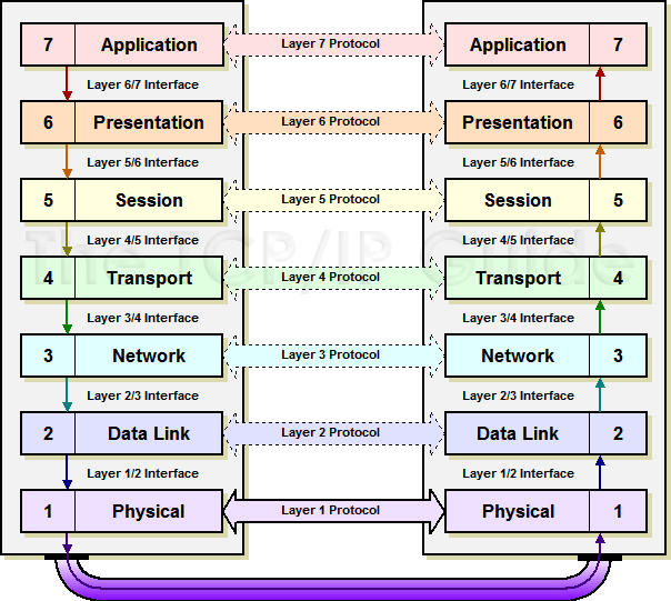
The packets from a higher layer are encapsulated
with headers (and trailers) that tell the peer about the packet
(IP headers say who sent the packet, where it is going, type of packet, length
of packet, checksum, etc.). The result is sent down to the software
implementing the next lower level. The entire packet received from above is
treated as data (headers and all) and the result is encapsulated again. Only
when the packet arrives at the physical layer is it converted to electrical
signals that are transmitted out the NIC and onto a cable.
(Show Diagram: |D| --> |HD| -->
|HDD| --> |HDDDT|)
Duplex
There are three types of
Point-to-Point communication methods: simplex (one-way, e.g. a
megaphone), half duplex (either way but only one direction at a
time, e.g., walkie-talkie), and full duplex (simultaneous two way,
e.g. a telephone). In reality, most full duplex channels are actually two half
duplex ones, considered as one. (Analogy with a four lane road: one-way
street, tollway ramps (one way during AM, the other during PM), and two-way
street (say, two lanes in each direction).
ISO versus TCP/IP Terminology
The ISO uses completely different
terminology than is common practice for TCP/IP literature. This is often very
confusing. Unfortunately there is little chance to adopt a standard
terminology for networking.
In the U.S.A you will likely only run
into ISO terminology when setting up routing that includes OSPF or IS-IS
protocols, or when setting up international WAN links. Be sure to have a
networking dictionary of terms bookmarked from the Internet before you run into
such situations!
Kernel Configuration for Networking
Networking is handled by the kernel.
Each protocol (suite) is usually handled by one or more kernel sub-systems
(typically present as modules), as are the physical network interfaces, the
logical network interfaces (loopback, PPP), and various network services such
as security, routing, traffic shaping, etc.
If the required sub-system (or module)
isn’t configured in the kernel then that network service won’t be available.
In the case of Linux you may need to rebuild the kernel to enable/disable some
network sub-systems. In other cases all sub-systems are present in the kernel
(possibly as LKMs) and you need to use various tools and edit various
configuration files to enable or disable these. (Chapter 5 of Hunt
explains what is needed for several OSes.)
Lecture
5 — Using Wireshark (formerly called Ethereal)
Wireshark
is a network protocol analyzer. Be careful of marketing hype!
If it isn’t called a protocol analyzer, it won’t be able to dissect the
packets for you. Wireshark has a GUI interface and is easy to use.
An older and related tool is called tcpdump.
Both tools can capture network traffic that passes by your computers NIC, and
either display it in real-time, or save the traffic in a file that can be
inspected later. The standard network traffic capture file format is pcap (also
called tcpdump format). (See man pcap(3).)
So you can capture with one tool and analyze with another. Both these tools
are available for all Unix, Linux, Mac, and Windows systems.
To capture traffic passing by a NIC
that isn’t addressed to that NIC’s MAC address requires placing the NIC in promiscuous
mode. If your NIC supports that, it usually requires root privilege to
do so. (On Linux, use “ip link set
dev eth0 promisc
on|off” or “ifconfig
eth0 [-]promisc”. Use “ip link
show dev eth0”
to see status; look for “PROMISC”.)
Wireshark uses the
utility dumpcap to capture
packets, and that program is executable by root
or group wireshark members only.
If you add your username as a member of the group wireshark, you won’t need to be root (usually; depending
on the security settings of your system, regular users may not be permitted to
switch NICs into promiscuous mode for example).
This works best with a hub. If using
switched Ethernet (everyone does today) remember that a switch acts like a
multi-port bridge. Once it learns the MAC address(es) reachable through
some port, it only forwards traffic for those destinations, rather than all
traffic. This means your NIC will only see packets addressed to it, or broadcast
packets.
Commercial grade switches (which
should be used in any organization, even a SOHO if security monitoring is
desired) include a SPAN (Switched Port ANalyzer, also
called a mirror or monitor) port that copies the data from the TX
line on other ports on the switch. (Some vendors call this a mirror port.)
You can often configure multiple SPAN ports, or per VLAN SPAN ports. However a
limitation of SPAN ports is that under heavy load some packets will not get
copied to them.
Taps (or Test Access Ports)
are special (expensive) devices that you can insert between a router and
firewall or a switch. These generally have 4 NICs on them: one to the router,
one to the firewall/switch, and two to the NMS. (Traffic on the TX line on
each of the first two NICs is duplicated, one to each of the last two NICs.
The NMS will usually have 3 NICS (one for remote access). The two NICs
connected to the tap should be bonded (IPMP) into a single virtual NIC,
which will capture all traffic. (A PC with appropriate hardware and 4 NICs can
be turned into a “home-made” tap.)
Even with a switch, so much traffic
passes by that most of the packets are unimportant and unrelated to whatever it
is you are checking. Protocol analyzers allow you to filter the
traffic saved, rather than saving all packets. The tcpdump man page gives a good explanation of the capture
filtering options available for both tcpdump
and wireshark (ethereal).
Other capture options are which
interface(s) to capture from, how long to capture, how many packets to capture,
and how much of each packet to capture. (Usually only the headers are useful
for debugging, but it is possible to capture all or part of the data.) To save
memory (and file space) it is possible to not save the Layer 2 framing (Ethernet)
data, which often is not useful for debugging).
(Qu: how many bytes are required to
capture all Ethernet, IP, and TCP/UDP headers? Ans: look in RFCs 791 (IP) and
793 (TCP, which is bigger than UDP). Ethernet frames vary in size depending on
type; the IEEE 802 standards can tell you the various sizes.)
Wireshark shows captured traffic in
three panes. In the top is a list of packets (the list pane),
one line of info for each.
The middle pane shows the details of
the various headers of a single packet selected from the list pane, and is
called the protocol pane: raw (physical layer), Ethernet (data
link layer), IP (network layer), TCP/UDP (transport layer), and some higher
layer protocol details (e.g., HTTP). Other protocols are shown as well such as
RIP, spanning-tree, ICMP, ARP, etc. This data shows in collapsible,
hierarchical way.
The bottom pane shows the raw data in
hexadecimal (hex) (the raw pane). As you click on various header
fields in the middle pane, the matching data shows in the bottom pane.
Wireshark allows you to set color
filters. These filter color-code the captured traffic to allow you to
highlight the bits important to you.
Finally you can set display
filters, that don’t affect what was captured but is used to hide some
of the captured traffic from the user interface. Ex: display filter the
captured traffic to only show DNS packets.
The traffic also shows relative timing
(time between successive packets).
Wireshark can also show summary
statistics, analysis, and graphs of the captured traffic.
You can’t view the
contents of encrypted packets, only (some of) the headers. For HTTPS, you can
use a Firefox add-on, HttpFox.
(Demo.)
Lecture
6 — Data Link Layer and Ethernet
Ethernet is a commonly
used suite of protocols, electrical, and physical specifications for LANs.
Ethernet implements the bottom two layers of the OSI model. Initially every
vendor had their own standards and protocols for networking, so you had to use
a single vendor’s stuff. Once vendors got together and formed common standards
and protocols, everyone started using them.
The data link layer,
or just link layer, has other names too: A broadcast domain (since L2
broadcasts won’t cross routers), a LAN (since it is common, and best, to run
one network per data link), and segment. The term segment is
ambiguous, as some network folk refer to two parts of the same LAN as two
segments, if separated by a repeater or switch.
Data Link Hardware: amplifier
(boosts signal amplitude, including noise), repeater (uses regeneration
of the signal to output a clean strong signal), hub (a repeater with
more than two ports (or NICs)), bridge (a smart repeater that won’t
transmit packets if the source and destination hosts are the same side (i.e.,
in the same network segment)), and switch (a bridge with more
than two ports). Cables (UTP, cat. 5e), standards (e.g., 3+90+6 meters
cable length), codes (EIA/TIA 568-B wiring closet), and safety
precautions. (Bottom line: hire this part out or take some courses!)
MAC addressing (6 bytes, vendor
ID + serial No, broadcast=ffff.ffff.ffff), NICs (show output of ifconfig). MAC addr a.k.a. data-link
addr a.k.a. BIA (burned-in addr) a.k.a. HW addr.
Q: When the network is half-duplex,
what happens when two computers send at once? A: Listen first, then send only
if the media is available (i.e. wait for a lull in the conversation).
If collision, wait a random time interval and try again. Give up after a
certain number of attempts. Category: CSMA/CD (carrier sense, multiple
access/ collision detection). (Until Ethernet is replaced with the next big
thing, you don’t need to know this classification scheme — unless you plan on
taking a certification exam.) These features require precise timing and will
(usually) fail if the physical network is too large or if faulty cabling is
used.
Packet collisions are aborted with a
special 4 byte jam signal that takes the place of the FCS. (Any
value can be used as long as it isn’t a valid FCS.) The resulting partial
packet (less than 64 bytes) is called a runt. While a few
collisions (and hence runt frames) are normal, too many runts will cause
performance issues and may indicate a faulty NIC or cable.
Internally, a NIC contains a
transmitter (TX) and receiver (RX). The RX listens for quiet moments, and
tells the TX to start sending data. The RX continues to listen to the network,
and compares what it hears (sees?) to what the TX says it’s sending. If they
differ a collision is detected, and the RX instructs the TX to send the jam
signal:
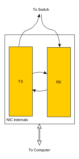
Modern networks use switches not
hubs (A switch is a “smart” hub, that learns which destination addresses
are connected to which NICs, and only transmits the packet to the NIC where it
needs to go), providing full-duplex. (Full-duplex Ethernet uses two twisted
pairs, not one as in half-duplex. Each pair is essentially a simpex channel,
so no collisions are possible.)
High end switches buffer packets
internally, so collisions are not possible in the switch. Note Ethernet (or a
variation) is still used, it is well understood and it just works. Known as switched-Ethernet.
Others: fast- (100MB) and gigabit-.
If a single host is
connected to two or more networks (usually by having multiple NICs) it can
(with the right software) forward packets from one net to the other. Such a
host is multi-homed and it can act as a gateway (or router;
discuss).
Ethernet Framing
The packets of data at this layer are called frames
and the headers are referred to as framing. (IEEE prefers the term protocol
data unit or PDU.) Ethernet was developed at Xerox in 1970s; other
versions later by DEC, Intel, and Xerox (DIX). Four types of Ethernet are in
common use today, most controlled by IEEE stds.
It is useful to know
this, since it can help in planning and trouble-shooting network issues.
DIX is known as Ethernet I. This was revised in 1985,
as Ethernet II, and is the most commonly used today (Ethernet I is no
longer used):
|
Ethernet II
|
preamble
|
Dest
|
Src
|
EtherType
|
Data
|
FCS
|
|
(# bytes)
|
8
|
6
|
6
|
2
|
46-1500
|
4
|
Ethernet II doesn’t use LLC so there’s only a MAC
header (shown in green) of 14 bytes, plus a trailer of 4 bytes.
The preamble is used to allow the transmitter and
receiver to synchronize to each other.
The Frame Check Sequence is a CRC
(similar to a checksum). The EtherType field says what the data
is (i.e., where the NIC driver should send it). For example, an EtherType
value of 0x0800 signals that the packet contains an IPv4 datagram, and 0x0806
indicates an ARP frame.
Padding may be needed to make the minimum data portion
size=46 bytes.
The entire packet
must be between 64 and 1522 bytes, not counting the preamble, but including
the 18-22 bytes of headers and the trailer. This is true for all four types of
Ethernet.
(It seems that the
packet sizes (max and min) were chosen to maximize efficiency on the hardware
available at the time. See community.cisco.com
for a more detailed explanation.)
Qu: since Ethernet II packets have no length
field, how does the receiving NIC know when it has seen the whole packet? Ans:
When the voltage on the wire returns to zero for a while, the full packet has
been received.
Ethernet devices must
allow a minimum idle period between transmission of frames known as the interframe
gap (IFG) or interpacket gap (IPG). It provides a brief recovery
time between frames to allow devices to detect the end of one frame, and to prepare
for reception of the next frame. This gap is the time it would take to
transmit 12 bytes.
The NIC checks the last 4 bytes it received (the FCS) against
the FCS it calculates as the data is received. If they don’t match, the frame
is discarded and never reaches the memory buffers in the host.
When standardizing the MAC header the IEEE replaced the
EtherType field with a Length field instead. This type is rarely used
since there is no type field; Novell and other proprietary protocols used 802.3
frames since there was only one type of packet and no type field was needed:
|
802.3 Ethernet (raw)
|
preamble
|
SFD
|
Dest
|
Src
|
Len
|
Data
|
FCS
|
|
(# bytes)
|
7
|
1
|
6
|
6
|
2
|
46-1500
|
4
|
With 802.3 the preamble is specified as 7 bytes, plus
the SFD=start of Frame Delimiter. Today 802.2 Ethernet is more common.
It adds a 4 byte LLC header:
|
802.2 Ethernet
|
preamble
|
SFD
|
Dest
|
Src
|
Len
|
DSAP
|
SSAP
|
Control Field
|
Data
|
FCS
|
|
(# bytes)
|
7
|
1
|
6
|
6
|
2
|
1
|
1
|
1 or 2
|
variable
|
4
|
The LLC header (shown in blue) includes: Destination
Service Access Point (DSAP) of 1 byte, Source Service Access Point
(SSAP) of 1 byte, and Control Field of 2 bytes (1 byte is also
allowed). The DSAP is the most important, taking the place of the EtherType
field of Ethernet II. 802.2 doesn’t increase the frame length so the max data
length would be 1496 or 1497 (1518 minus the 21 or 22 bytes of header). Note,
the frame length was increase in 20xx to 1522, making the max data length 1500
or 1501 bytes today.
SNAP (subnetwork access protocol) is an
extension to the 802.2 LLC, needed since at some point there were more
protocols than could be defined by the one-byte DSAP field. The Ethernet SNAP
(a.k.a. 802.2/SNAP) looks like this:
|
Ethernet
SNAP
|
preamble
|
SFD
|
Dest
|
Src
|
Len
|
LLC
|
Org
Code
|
Type
|
Data
|
FCS
|
|
(# bytes)
|
7
|
1
|
6
|
6
|
2
|
3 or 4
|
3
|
2
|
variable
|
4
|
The SNAP header (shown in orange)
adds 5 bytes to the existing LLC field: Organizational (or vendor)
Code (3 bytes, often the same as the first 3 bytes of the source MAC), and Ethernet
Type (2 bytes).
Notice how the max frame
length doesn’t account for SNAP headers; using these reduces the amount of
actual data in a frame! The overall size is still at least 64 bytes and at
most 1522 bytes.
Once VLANs were
invented, more bytes of header were needed to specify to which VLAN a packet
belongs. 802.2ad increased the maximum frame size from 1518 to 1522, but even
that means that VLAN and/or SNAP headers will reduce the maximum data in a
frame below 1500 bytes, or else a giant frame results. Giants
may or may not cause problems on the LAN.
The IEEE VLAN tag (802.1Q),
if present, is 4 bytes and is placed between the Source Address and the
EtherType or Length fields. The first two bytes of the tag are the Tag
Protocol Identifier (TPID) value of 0x8100. This is located in the same place
as the EtherType/Length field in untagged frames, so an EtherType value of
0x8100 means the frame is tagged, and the true EtherType/Length is located
after the tag.
Ethernet overhead
depends on which version is used. The worst would be 802.2/SNAP (and 2 byte
control field in the LLC): 1491 bytes of data per frame, and 1518 + 12 (IFG) +
8 (preamble) = 1538 bytes per frame, or 47 bytes of overhead per frame.
All systems have a utility to examine
and tweak the Ethernet parameters of a NIC. Linux has mii-tool (Show mii‑tool ‑v) and Solaris has ndd or (the more modern) dladm. Some parameters may be set
using ifconfig (and/or ip on Linux). However most Unix (and
Linux) systems have or can install and use ethtool [‑S] eth0. (“-S” provides statistics.) This tool works very well (and
learning one tool is simpler than learning several). (Demo.)
To see which frame
type your NIC (and switch) is using, use wireshark.
Token Ring Framing
Developed by IBM in 1980s.
Passes tokens.
Start Delim (SD), Access
Ctl (AC), Frame Ctl (FC), Dest addr, src addr, data, FCS, end delim (ED, frame
status (FS)
L2 addressing (MAC, Hardware, BIA)
Two parts: IEEE
manufacturer ID (block ID or Organizationally Unique Identifier
(OUI)) plus Device ID. Written in hex, usually can’t be changed by OS
utilities. (Show on computer in class.)
L3 addressing
Network address, allows a
hierarchical scheme, can be assigned via OS utilities. Note all
addresses are associated with NICs and not with hosts!
Qu: Why have two different
addressing schemes, L2 (MAC) and L3 (network) addresses?
IEEE 802 Standards
802.1: Standards related to
network management. These include 802.1d (spanning tree), 802.1q (packet
tagging for VLANs), 802.1x (security), and 802.1ax (link aggregation).
802.2: General standard for
the data link layer in the OSI Reference Model. The IEEE divides this layer
into two sublayers: the logical link control (LLC) layer and the media access
control (MAC) layer. The MAC layer varies for different network types and is
defined by standards IEEE 802.3 through IEEE 802.5.
802.3: Defines the MAC
layer for bus networks that use CSMA/CD. This is the basis of the Ethernet
standard. This layer also defines Ethernet Link aggregation (802.3ad),
although the newer 2008 IEEE project 802.1ax is designed to replace it.
802.4: Defines the MAC
layer for bus networks that use a token-passing mechanism (token bus networks).
802.5: Defines the MAC
layer for token-ring networks.
802.6: Standard for
Metropolitan Area Networks (MANs).
802.7: Broadband standards (media,
interfaces, and other equipment).
802.8: Fiber-optic media
and technologies.
802.9: Standards for
transmitting voice and data over a single medium (VoIP).
802.10: Various security
topics: access control, encryption, certificates, etc.
802.11: Wireless standards,
including the popular 802.11b (Wi-Fi).
802.12: High speed
networking standards (>100 MBPS).
(Many of the 802 standards
are available for free from standards.ieee.org.)
There are a number of
popular but propriety protocols in use. For example, the Cisco dynamic
trunking protocol (DTP) used to connect VLANS.
Data Transmission Issues
point-to-point
- a single transmitter at one end and receiver at the other. (This may apply
to a transceiver at each end too.) Network addresses for one
destination are called Unicast addresses.
broadcast -
(or point-to-multipoint) One sender, many receivers. All
receivers on a network receive the transmission. (All the speakers throughout
a school bldg.) (Not available for IPv6!)
multicast -
(or webcast) one sender, receivers subscribe (or tune in) to
transmission. (Think of a radio or TV tuner.) Senders and receivers can use
special protocols to find each other on an internet and to create an optimal
transmission path; requires smart NICs, switches, and routers. Multicast
requires hosts and routers that support IGMP (Internet Group Management
Protocol) in IPv4. (IPv6 uses ICMP for this.)
anycast - one
sender, any one of several receivers. (E.g., routing protocols, load-balancing
in a cluster.) Global Anycast is a term used by content delivery
network operators, such as CloudFlare and Akami, to describe how they mitigate
dDoS attacks.
Capacity
throughput -
How much data (not necessarily information due to overhead) is
transmitted (past a single point) in a given interval of time. a.k.a. capacity
or bandwidth (technically a different concept). (bps=bits per sec, !=
baud.)
bandwidth -
The difference between the hi and low frequency that a medium can use for data
transmission. This can also be calculated as 1/Tb, or the inverse
of the time it takes to transmit one bit of data. Note that modern
communications generally use multiple channels simultaneously. The higher the
bandwidth, the higher the possible throughput is. (Nyquist law states
the max throughput is always less than or equal to twice the bandwidth.)
Both throughput and
bandwidth can be measured in bps. Sometimes, bandwidth is measured in Hertz
(cycles per second). The conversion of Hz to bps depends on the encoding used,
the amount of power used, where in the spectrum the band is located, and
possibly other factors. (See Shannon’s
Law.) For example, digital TV (DTV) channels are each assigned 6
MHz bandwidth, but each channel provides almost 19 Mbps, not 12 Mbps. (Since
HDTV requires about 1 Gbps, a lot of compression must be done on the data
before transmission.)
When trying to estimate
required capacity, the data transferred is only half the story. All data is
wrapped in layer 4, 3, and 2 headers. This adds up to dozens of bytes per
packet, regardless of the amount of data in the packet. If sending small
messages of say 20-40 bytes (e.g., HTTP GET packets) this overhead adds up to
over 50% of the used throughput. Additionally many packets are sent as
overhead, such as routing protocol packets, ICMP packets, spanning tree
packets, keep-alives, DHCP and ARP broadcast packets, etc. On a typical 100
Mbps Ethernet LAN, only about 50 Mbps is available for useful data!
Transmission problems
EMI/RFI -
Electro-Magnetic Interference/Radio Frequency Interference (Motors, radios/electronic
devices, machines, florescent lights, ...)
attenuation -
loss of signal strength (loss and spread-out of signal). Often a limiting
factor of maximum segment length.
latency - the
delay measured from when a bit is sent to when that bit is received. Every
network device has some latency. A typical enterprise grade switch found in a
large data center might have 10-30 µs per switch, with data often needing to
cross 5-6 switches. (Routers have much higher latencies often in the tens or
hundreds of milliseconds (ms). Going from an application in user-space to or
from a NIC is often another 60 µs. In fiber optic cable, light has a latency
depending on distance; it travels about 122,000 mps. Electricity is slower.
Thus in a WAN, the distance is often the largest factor by far. (For
comparison, to get data from a spinning disk often requires 5 ms, or about 800
times as long; from DRAM to a CPU is about 100 µs.)
All the latencies add up
(are cumulative), and impose a very real limit on the type and size of
large (web-scale) applications. New research (2015) is working on new hardware
and techniques to reduce total latency in a data center to under 15 µs.
Crosstalk -
when a signal from one pair in a cable puts a signal (i.e., noise) on another.
Crosstalk is measured in decibels (dB). Using twisted pairs reduces crosstalk,
the more twists per foot the better. The twist ratio is the
number of twists per foot in twisted pair (TP) cables. When there is more than
a single wire pair in a cable, it is common to have the different pairs use
slightly different twist ratios. (So the exact twist ratio per pair in say cat
5 cable varies between manufacturers.)
Alien crosstalk is
noise from adjacent cables. This can be a problem when UTP cables are bundled
closely together in a conduit.
A model doesn’t enable
communication. It defines functional specifications for a group of protocols,
which implement the model. The protocols in turn are implemented by actual
software and hardware.
Ethernet allows 1,024 nodes
maximum per (V)LAN, but a more practical limit is 254 nodes (makes
subnetting easier), limited by available and desired throughput.
The maximum segment
length depends on attenuation, latency, and segment type. (Populated
segments contain end nodes; transit segments don’t, and can be much
longer.)
Physical Layer Networking Standards
These standards are all named “speed Base|Broad distance”,
where speed is the capacity in megabits per second, “Base” indicates
baseband transmission, “Broad” indicates broadband transmission, and distance
is approximately the maximum distance. (If the distance includes the letter
“T” then the maximum distance is 100 meters with a maximum of 1024 nodes per
segment. The letter “X” here indicates full duplex capability and faster
signaling. The letter “F” indicates fiber optic cabling is used.)
The meaning of broadband
depends on context. Originally used (in telecommunications) to denote a single
channel that used all of the available frequencies in the “band”. In contrast,
a baseband signal used only the some of the frequencies (the frequencies
above the channel’s coherence bandwith
are less desirable), leaving some available for sideband transmission.
In this sense, broadband is similar in meaning to wideband. Such
signals may require more expensive antennas and more circuitry to process, but that
may be needed if you need the higher throughput in a given band (for example,
sending music without losing the highs, compared with voice or even just morse
code transmission).
Within digital communications, the term
refers to transmission over multiple channels, which allows for a higher
throughput. In this context, baseband refers to a single channel.
Finally, within networking and especially
the Internet, marketers from ISPs used the term loosely, to denote their
service was faster than dial-up modems. Over time, the origin of the term was
lost and it simply means faster. To prevent marketing fraud, various
governments around the world have set standards for Internet throughput speeds,
in order to label a connection as broadband. (The same is true of other terms,
such as “3G” and “LTE”.)
In the U.S., the FCC (under a congressional
mandate to report annually the state of broadband) set the original meaning of Internet
broadband as 200 Kbps or more in at least one direction; after 1996 (I think),
the definition
was refined to 768 Kbps down and 200 Kbps up. In 2010, recognizing
that Internet traffic wasn’t mostly text anymore, the definition changed to 4
Mbps down and 1 Mbps up. Currently (2015), the FCC
is proposing another change from this 4/1 definition, to 25 Mbps
down and 3 Mbps up.
|
Name
|
Description
|
|
10Base2
|
(also thinnet), a (thin) coax cable with
a maximum distance of 185 meters. ppt31
|
|
10Base5
|
(also thicknet), a (thicker) coax cable
with a maximum distance of 500 meters.
|
|
10BaseT
|
UTP or STP cable with a maximum distance of 100
meters. Commonly used for Ethernet.
|
|
100BaseT
|
UTP or STP cable with a maximum distance of 100
meters.
|
|
100BaseTX
|
UTP or STP cable, a maximum distance of 100 meters,
and full duplex capability. Commonly used for Fast Ethernet.
|
|
1000BaseT
|
Also 1GBaseT; newer standards along with 10GBaseT.
|
|
10BaseF
|
Fiber cable with a maximum distance of 2 or 3
kilometers (depends on type of fiber used).
|
|
100BaseFX
|
Fiber cable with a maximum distance of 2 or 3
kilometers.
|
Physical
Design (wiring) Concepts and Terminology
EIA/TIA-568 - Commercial building
wiring standards. Also called structured cabling or cable
plant.
MDF - Main Distribution Facility, the
central wiring closet. This should be located close to the POP. It
often includes the telecommunications closet or telco room,
which contains punch-down blocks and/or patch panels,
and the cross-connect.
IDF - Intermediary Distribution
Facility refers to wiring closets other than the MDF. May also be called a telecommunications
closet or telco room. (EIA/TIA-568 requires at least one IDF or MDF
per floor.) (5-4-3 rule.)
Demarcation point (or demarc)
is the protected, grounded, physical connection point where the private network
(the subscriber wiring) connects to a public network (the local loop) or ISP’s
wiring.
POP or Point of presence
is the connection point to the Internet. This includes routers and possibly
other network devices. The POP may reside in space owned or rented by the ISP
or may be located on the customer premises. (The POP and demarc are often
located in the MDF.)
Vertical wiring connects wiring
closets together. Also called backbone wiring or risers,
this includes cabling between the MDF and IDFs, and cabling between buildings.
(This term should not be confused with the backbone network.) ppt61
Horizontal wiring connects
workstations (and servers not in a wiring closet already) to a wiring closet. Max
dist is ~100m: 3m from workstation to jack, 90m from jack to wiring closet, 6m
inside. (In practice, you may need more than 3m. This is okay,
provided you remain under the 100m total.)
The catchment area
is an area on one floor of a building that is served by a wiring closet. Under
ideal circumstances, a centrally located wiring closet may serve a catchment
area with a 100-meter radius. (Often each catchment area is associated with a
LAN segment.)
Fiber
Optics
Fiber optic cables are used
for nearly all long-distance communications today. They are increasingly used
for LANs as well. A Sysadmin should know something about this technology.
The heart of a fiber
is a 9 µm (micrometer, or a millionth of a meter) wide strand of glass, known
as the core. This core is nearly perfectly transparent to infrared
laser light (1.55 µm wavelength). The core is surrounded by 50 µm of glass
with a different refractive index, known as cladding. The boundary
between the two acts like the surface of a lake, trapping any light in the core
(it reflects off the cladding). The cladding in turn is surrounded by a
protective coating. One to several hundred fibers are bundled into a single
cable.
What are the limits? Light
pulses travel down the fiber at two-thirds the speed of light in a vacuum.
Also, photons will occasionally bounce off some glass atoms and scatter out to
the cladding. After 50 km (about 30 miles), 90% of the original light is
lost. Originally that meant expensive signal regenerators, but in the 1990s a
way was found to amplify the light in the fiber without such devices. Such
cables only needed the regenerators every few hundred miles, if that. Such
fibers can also have their bandwidth divided into nearly 100 separate channels,
which due to the desirable properties of light, do not cause crosstalk issues.
Another limitation is noise
induced at the light source. While a stronger light can travel further, the
stronger the signal, the stronger the noise, which is self-defeating at some
point.
The final limitation is
that the light pulses spread out over long distances, meaning you cannot
shorten the light pulses too much or one will drown out the next. However, the
light can be encoded by phase and other means to allow multiple bits of data
per pulse.
By the year 2,000, the
fiber cables could carry 800 Gb/s, which at the time seemed like a lot.
Overbuilding of cables by dot-com companies had left in their wake large
amounts of such cables throughout the U.S. With nobody using them, they became
known as dark fiber. (Google and others have started to use this.) The
legacy of this cable infrastructure means no companies want to dig it up and
replace it all with larger capacity cables, but clever tricks to increase the
throughput are hitting physical limits. New fibers (2016) can carry nearly 10
Tb/s per fiber, enough for 380,000 people to stream Ultra HD Netflix.
Lecture 7 — TCP/IP Overview
TCP/IP are a set of protocols for
layers 3-7. Often used with Ethernet. TCP/IP protocols (and many other
protocols) are documented in RFC documents.
TCP/IP includes 2 major protocols for
layer 4: TCP and UDP. TCP is for connection-oriented
communication while UDP is connectionless. With TCP, it takes a while to setup
the connection, but once set up data is sent quickly and reliably. If sending
a file for instance, TCP will break up the data in packet-sized segments,
send each segment as an IP packet, and reassemble the segments at the
destination. Error checking is used to prevent lost, corrupted, duplicate, or
out of order packets. This is done using timeouts, sequence numbers, and
acknowledgements for each segment sent.
Other IP transport
protocols have been defined but few are widely implemented. One worth knowing
is SCTP, the stream control transmission protocol. SCTP is defined in
RFC-4960 (written in 2007), with an introduction in RFC-3286.
SCTP is supported in
*nix and some Windows versions. Wikipedia has a good page on this. Basically,
it combines the message-oriented nature of UDP with the reliable transport
features of TCP. It also supports multi-homing (inherently, by associating
several IP addresses with the source and/or destination) and multiple
independent streams via a single connection (so TCP keep-alive which
never worked all that well, is not needed); each stream can use more or less
SCTP reliability features.
UDP on the other hand is
a single packet (or datagram) sent with no error checking or acknowledgements.
(It would be up to the application to perform any error checking or
acknowledgements, if desired.) UDP is thus very quick.
TCP/IP includes many other protocols,
such as ICMP (ping uses this), RIP (routers use this), etc. The
different protocols are assigned protocol numbers in the file /etc/protocols. (Show)
Addressing
(and Binary Numbers Review)
Review binary numbers. (Qu: why used?
Ans: history of computers: analog, then decimal, then binary as cheapest and
most reliable, even though not easiest for humans.) (Show Binary number web
resources.)
Qu: Why not use MAC address? Ans: Huge
unmanageable routing tables, administration problems (firewall). Logical,
routable (L3) addresses are needed that (a) can be assigned
administratively, and (b) can be summarized. IP addresses have two parts:
network number and a host number. (Sometimes a subnet is used too.) The idea
is that routers only need to keep track of network numbers. Once a packet is
delivered to the right LAN, the data-link protocols (Ethernet or Token ring)
will make sure it gets to the right host. The ARP protocol is
used to map IP addresses to MAC addresses.
IP addresses are 32 bits long.
(This isn’t a lot of addresses! This will change for IPv6.) They are most
commonly written in dotted-decimal notation: 10.3.200.42. The
32 bits are divided into the network portion and the host portion. Some
network numbers identify larger networks and others smaller networks. Each LAN
must have a unique network number, assigned by the IANA (or your local ISP who
bought a bunch of them and leases them out).
Originally, there were three sizes of
networks you could get. The class or size of a network is
determined by the first byte of its IP address. The range of network numbers
for large networks are 1–126. These are known as class A networks
(these are huge, up to 24 million hosts per network). The range 128‑191 are
known as class B (up to 65 thousand hosts per network). The range
192–223 is for class C (up to 254 hosts per network). IP addresses that
begin with a different first byte are used for different purposes
(multicasting, research) and are reserved. Note your own computer always has
the address 127.0.0.1. (The loopback address, usually
referred to by the name localhost.)
A list of private,
reserved, or special purpose IP addresses can be found in BCP-153.
The class determines how many bits of
the IP address refer to the network and how many refer to the host. A class A
address uses the first byte only for the network number (and the number zero is
reserved), so there are only 126 such networks possible. Qu: what class is
200.32.7.18? What is the network number (200.32.7.0) and host number (18)?
A class B network uses two bytes for
the network and two for the host.
A class C network uses three bytes for
the network and one for the host.
A network is referred to by an IP
address with the host number set to all zeros. A directed broadcast
for a network uses an IP address with all-ones for the host number. Thus, no
host computer can be assigned a number of all zeros or all ones. An IP address
of 255.255.255.255 (all ones) is a local broadcast address,
destined for all hosts on the same network as the sender.
IP
Addressing on the Internet
Originally provided informally by Jon
Patel, who reportedly kept track of assignments in a small notebook. As the
Internet outgrew this method, the NSF formed the InterNIC (www.internic.net) to allocate address
blocks (under an exclusive contract from Network Solutions).
Later NSFNET was de-commissioned and
the assignment of IP addresses passed to other organizations. Ultimately, they
are under the control of the IANA and the ICANN IP address assignment
support organization (ASO at aso.icann.org).
The internationalization of the Internet meant the various countries (or
regions) set their own pricing, procedures, and policies (the ASO policies are
very liberal and brief). Today, there are a number of Regional Address
Registrars (RARs). For North America, the RAR is ARIN (www.arin.net).
(Show.)
Provider Independent (PI)
address blocks are used for tier-1 ISPs, Internet Exchange ISP members, and
larger multi-homed organizations. The past liberal policies for giving these
out has resulted in the 192/8 –205/8 swamp. (And many required routes.)
By giving huge blocks of addresses to
the RARs, who in turn carve these up hierarchically to their customers (the
larger ISPs, who do the same thing), the routes can be aggregated (many routes
going to the same geographical region can be combined into a single route). Today
RARs rarely give out addresses; you get them from various tier 2 and tier 3
ISPs.
Show IPaddrExhaustion.htm
showing available blocks from 1993 to 2011. A: As of 2/2011, there are no
IPv4 address left from IANA! The RIRs got the last of it, and now they too are
running out. In 4/2014, ARIN reported it had about 16M IPs left, and LACNIC
said it is none. In 6/2014, Microsoft ran out of U.S. IPs for its U.S.-based Azure
cloud service; it is temporarily using its pool of foreign IPs for U.S.
customers. (This tactic makes it difficult to run geolocation services, and
can’t last long.)
Update: as of 6/2015, ARIN is
out of large IP blocks (it does have a limited number of /8 blocks left). Only
Africa still has large blocks left. Everyone else must use a waiting list, or
get blocks by buying them directly from the holders.
Cybercriminals are
setting up shell companies and hijacking defunct IPv4 addresses, re-registering
them and selling them to desperate companies, according to Naked Security.
About 25 hijackings were reported since September, up from the 50 that took
place during the previous 10 years. (From Naked
Security, 2016-06-21)
Subnetting
A large organization might use a class
A or B network. But if the company is larger than one location many LANs (and
thus many networks) will be needed. Rather than use (and register and pay for)
many class C networks, a company would like to use one class A or B network and
sub-divide it into many smaller networks. This subdivision is never seen by
the outside world (who still just sees the one network). Such networks are
called subnets. Using subnets the local network administrator
decides what network number to assign each LAN, and how big a network to
allow. Note that all workstations, servers, and routers on a network must know
about the subnet it is on (so a host can tell when to send a packet directly
and when to use a gateway).
With subnets knowing the class of an
address isn’t sufficient to allow a host to determine its subnet number. A
second 32 bit value is used to show which bits in the IP address represent the
network (including the subnet) and which represent the host number. This value
is known as the subnet mask or simply the mask:
172.16.100.21 = 10101100.00010000.01100100.00010101
255.255.240.0 = 11111111.11111111.11110000.00000000
| network | host |
| sn |
A shorthand notation for the subnet
mask is to just show how many bits are set to one: 172.16.100.21/20. In this example our company paid for
one Class B network (of 65,534 hosts) and then internally carved out 16 subnets
of 4,094 hosts each. (Note: some older routers incorrectly don’t allow subnet
numbers of all ones or all zeros. You should avoid using these subnet
numbers.)
CIDR
Confused? Then you’ll be happy to know
the modern Internet has dropped the whole scheme of classes and subnets.
Instead, all IP address simply have a network number and a host number. The network
mask (or just mask) determines which bits in an IP address comprise the network
portion, just as with subnets. Such classless IP addresses are used in
modern routers. The process is known as CIDR (Classless Inter-Domain
Routing).
CIDR makes efficient use of the IP
address space: an organization can get a network number for the exact size
network they need. A problem with CIDR is that there is no sub-netting, so an
organization must lease official IP network numbers for each LAN they have.
Many organizations still use class addressing with subnets. CIDR is considered
an interim solution to the shortage of network numbers, until IPv6 becomes
widely adopted.
Illustrate
how host determines MAC address:
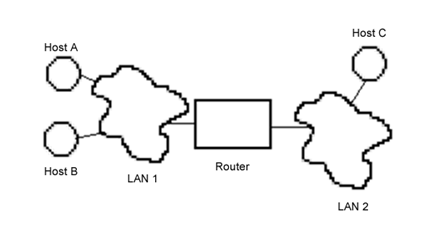
(1) Source
(local) host A determines if destination (remote) host B or C is on same
network (LAN). If so, then (2) broadcast ARP request for destination host B’s
MAC address. If not, then broadcast ARP request for gateway (a router
that can connect one network to another). (3) Wait for ARP reply. (4) Now
send packet to destination (gateway), with Router’s (LAN1) interface’s MAC
address but host C’s IP address.
Hosts maintain an ARP cache to save a
lookup. To view the ARP cache use the command arp -an. (Show.)
RARP (which is related to BOOTP
and DHCP protocols) does the reverse: Given a host’s MAC address (which
is all the host typically knows when it boots up) it asks a server to tell it
the IP address.
A single NIC may have multiple IP
addresses. This is known as IP aliasing.
TCP/IP
Protocols
The sub-protocols of TCP/IP
include IP, ICMP, ARP, (L3), and TCP, UDP (L4), as well as several others not
discussed here.
TCP/IP was design to
implement a four layer model: Application (corresponds to L7-L5), Transport
(L4), Internet (L3), and Network (L2-L1). The term network was
confusing since the OSI L3 is named network too, so this layer was renamed to host-to-network
or Network Interface. For most certifications the application layer
protocols and the network interface protocols are minimized, perhaps because at
the bottom your choices are limited (Ethernet for LANs) and applications vary
so much between platforms and configuration options.
IP
This L3 Protocol is used to
send IP datagrams across an internet. (The individual networks
in an internet are often referred to as subnetworks or more
simply subnets.) The current version of IP is version 4 but a
new version, IPv6 (sometimes IPng), will replace it someday
(Internetv6 is already “on-the-air”, and many applications such as the Apache
web server will already work with IPv6 addresses and protocols. The following
relates to IPv4.)
The IP packet contains data
(from L4) and headers that enable routers to transfer data, and hosts to
receive and reply to packets. An IP packet can be 65,535 (64K) bytes long
max. (See fragmentation, below.)
IP is considered an unreliable
protocol, not because if fails often but because it offers connectionless
services (no error control or segment reordering).
Understanding the IP
headers (and other TCP/IP headers) is vital when troubleshooting, understanding
a network, or configuring firewalls or other applications. The fields are:
Version, Internet header
length (in 32-bit words), Differentiated Services (used to be Type of Service,
or TOS), Total length, Identification, Flags, Fragment offset, TTL (Time-to
live), protocol, Header checksum, Source IP address, Dest IP address, Options,
padding, data.
The TOS field was
often ignored (Win NT4 servers always set to hi priority to make them seem
faster) in traditional networks. It has been replaced in modern IP with
differentiated services field (“DS field”) and the ECN (explicit congestion
notification) field. This can be useful in mixed voice/data nets, or when and
ISP offers a higher quality of service, or to push interactive data ahead of
email and file transfer traffic on a cable or DSL modem. ECN is used by
routers to tell the sender to slow down.
Fragmentation
Suppose a file of 10,000
bytes is sent. Since this won’t fit into a single TCP/IP packet (or Ethernet
Frame), the file must be sent as a series of packets. Even if the data to be
sent was under 64 KiB, and thus would fit into an IP packet, it still must be
split into smaller IP packets that the NIC (and Ethernet) can handle.
The max size is called the MTU,
for maximum transmisison unit. This is the max number of bytes your NIC
can handle in a single frame, usually 1500-ish. If the IP software in your
computer is handed a packet larger than the MTU, it will split it up into
multiple IP packets instead of sending one large one. This fragmentation
occurs at L3. Note the headers from L4 and higher layers appear to the IP
layer as just part of the data to be sent. So, only the first packet in the
series is likely to have L4 and other headers, plus some of the file data. The
rest of the packets will not have the L4 and higher headers, just the remaining
data (and of course the IP headers). All but the first packet in the series
are call fragments because they don’t each have a complete set of
headers. The fragments are reassembled at the destination, back into the
original packet.
Wht happens with ARP
or other protocols not encapsulated in IP packets? Most such protocols have
tiny and fixed packet sizes, so the problem of fragmentation doesn’t arise.
The rest must either handle fragmentation, or (more commonly), simply encapsule
their packets inside of IP packets.
Note that when using
packet capture software such as Wireshark, on the sending end you will probably
only see the large packet to be sent, before fragmentation. At the
destination, you can see the multiple IP fragment packets arrive.
The Identification
field is used when an IP packet must be fragmented. Each fragment of
the original, oversized packet is sent in a different IP packet, but all with
the same identification number. The flags field is also used to control
fragments, and to indicate the last fragment.
In order to reassemble the
fragments in the correct order once they all arrive at the destination
(remember the packets may arrive out of order), a fragment offset
is used to indicate which part of the application data in contained in the
packet. Let’s say the first packet contains mostly headers and 100 bytes of
the file data. Then the second packet will have an offset set to 100 (actually
99 since the numbering starts at zero), and so on until the last packet. All
the packets for this file will have the same identification, and the flags will
indicate when a packet is the last one of the original (un-fragmented) packet.
TTL
TTL (Time To Live)
indicates the max time (in seconds) that a datagram will be allowed to remain
on the network before it is discarded. Although routers are fast it is
required that each router decrement the TTL by at least one. It is quite
common to have each router subtract exactly one so the TTL field in practice
indicates the number of hops (different networks) a packet can go
through before the destination is so far away it is considered unreachable.
The TTL is sometimes referred to as a hop count. The TTL field prevents
bad routes from looping a packet around an internet forever: when a network
device receives a packet with a TTL of zero the packet is discarded.
The TCP/IP specification
states that the TTL field for TCP packets should be set to 60 [RFC-793] when first
sent but many systems use smaller values such as 30 or even 15. The maximum
possible value of this field is 255, and many systems set the TTL field of ICMP ECHO_REQUEST packets (which are
sent by ping) to 255 rather than
60. This is why you will sometimes find you can ping some hosts but not
reach them with telnet or ftp.
In normal operation ping prints the TTL value from the
packet it receives from a remote system. But remote systems set the TTL in the
reply to different values: sometimes 255, sometimes 128 (the loopback
address often uses this value), sometimes the correct value of 60, and
sometimes some other value. In some cases, the remote end uses the TTL value
from the request packet unchanged in the reply, so the TTL value you see will
be 255 minus the round-trip number of hops.
The protocol field
shows the L4 packet type contained in the data. This allows the IP software to
send the data up to the correct L4 protocol software.
The Header checksum
is for the L3 header only.
Options are rarely
used for Ethernet (use usually indicates hacker activity) but can be used in
Token Ring networks for source routed packets (the route is recorded in the
options field).
Padding is used to
make the head a multiple of 32 bits (4 bytes).
TCP
Transmission Control
Protocol is the L4 protocol used to provide connection-oriented services.
TCP provides error control (and is thus considered reliable),
flow control, and packet (or segment) reordering. TCP requires
that a connection be established before it can be used and torn down after you
are done (via a process known as a handshake, described
later). While it is “up”, the connection is easy to use by applications. In fact,
the service appears to be an error-free virtual circuit, so applications don’t
need to deal with missing, duplicate, or out of order packets. However, it
does take some extra resources (and time) to establish the connection. (TCP/IP
defines another L4 protocol, UDP, which can be used when TCP services aren’t
needed.)
When one host has sent the
last packet, they tear down their side of the connection. While either host
can abort both sides of the connection by sending a packet with the RST flag
set, more commonly the process is more orderly. After sending the last packet,
a packet with the FIN bit is set, and the value the host expects in the final
ACK. When that ACK is received, that half of the TCP connection is considered
down and no further packets sent need be processed. When the other side also
sends a FIN packet, and receives the ACK, the entire connection is considered
finished. This is usually four packets, but the second host may send a FIN,ACK
packet, so only three are exchanged. (Show in Wireshark.)
Beside optional connection
oriented reliable services, L4 is responsible for delivery of packets to the
correct application (L5 and L6 are optional and when present are often
implemented by the application itself). Each application can define one or
more data flows (example: web browser with multiple windows open). Each flow
is identified by a port number. A client application sends a
request packet containing a source port number. The destination port number
identifies the application (server) that the destination NOS (network
operating system) must deliver the packet to. To make things easier most
servers use a standard port number called a well-known port number.
(Show /etc/services)
The TCP packet header
fields are:
Src port, Dest port,
Sequence number, ACK number, Offset (TCP header length), reserved (6 bits, used
for congestion (flow) control), Flags (Codes), Window-size (used for sliding
window method of flow control), Checksum (covers entire TCP segment), Urgent
pointer, Options (this field may be omitted), Padding (if needed), Data.
TCP Flags: URG (Urgent),
ACK, PSH (Push), RST (reset), SYN (synchronize), and FIN (finished).
MTU, MSS, and
PMTUD
One of the options
that is sent with SYN packets is the MSS, or maximum segment size. Each
host calculates MSS as the smaller of the RAM buffer used to hold packets and
the NIC’s MTU (minus headers). After the handshake, the smaller of the two MSS
values is used. In theory that prevents any need for IP fragmentation.
However, if some network between the sender and receiver has a smaller MTU than
that, the routers in the middle will fragment and reassemble the packets.
If the sender
supports PMTUD (path MTU discovery, the IPv4 protocol used to
discover the smallest MTU between two hosts, RFC-1191), and
nearly all systems do today, it will use that to determine the MSS it
advertises. This works by guessing the smallest MTU on any network along the
path from the source to the destinationis the same as the sender’s MTU, and
setting the don’t fragment bit in the IP header. Any router whose MTU
is smaller will send back an ICMP fragmentation needed packet,
containing its MTU value. The sender then tries again using the smaller size.
This is repeated
until the packet get through. Then, all packets sent in the flow will have the
DF (don’t fragment) bit set. If the path changes in the middle of the flow,
the ICMP packet will arrive and the new lower MTU is used thereafter.
If the path changes
during a long IP conversation, the smallest MTU may be larger or smaller along
the new path. If smaller, the sender will receive the ICMP packet and adjust
accordingly. To discover larger MTUs, every so often (10 minutes for Linux and
Windows) the sender will increase its MTU and see if it works.
The major problem
with this scheme is that many organizations have their firewall drop all
incoming ICMP packets. To support IPV4’s PMTUD, you should allow some ICMP
packets in (type 3, code 4). With IPv6, this is required. If blocked,
sometimes a TCP or other data flow will start fine, then appear to hang (a black
hole connection, because the sent packets seem to vanish).
UDP
Connectionless (best
effort) delivery of datagrams. Headers:
Src port, Dest port, Length
(Whole datagram), Checksum
ICMP
Internet Control Message
Protocol is used to send control messages, not data. Typically, error messages,
but also echo, used for ping
and traceroute.
ICMPv6 not only
provides the functionality that's in IPv4 ICMP, such as conveying
unreachability or performing ping, but also includes Neighbor Discovery, the
IPv6 replacement for ARP, and other functions. With IPv6, it is more important
not to filter ICMP traffic within your organization’s network.
ARP
Address Resolution Protocol
is used to translate L3 (network) addresses into L2 (Ethernet) addresses. A
broadcast message is followed by a reply.
The tool arptables can be used to prevent some
hosts from learning about some other hosts, on a LAN.
Application Layer Protocols
TCP/IP includes protocols
such as telnet, ssh, FTP, SMTP, SNMP, and many others.
Other Protocol Suites
Novell’s IPX is similar
to IP with UDP, and SPX is similar to IP+TCP. Novell defines
addresses differently (a 32 bit network number plus a 48 bit host number, often
the MAC address is used) and has different protocols and packet types. Novell
servers can encapsulate IPX packets within TCP/IP packets, so two Novell
servers can communicate over the Internet.
Microsoft’s NetBIOS
(Network Basic Input Output System) originally designed for small,
Microsoft-only P2P networks (Windows for Workgroups). An application layer NetBEUI
(NetBIOS Enhanced User Interface) was added later. This works well for small
MS only P2P networks but doesn’t scale up well. With several dozen hosts
NetBIOS is inefficient, max is 254 hosts. Security is poor too. Finally, NetBIOS
addresses are L2 addresses and are thus not routable. Like IXP NetBIOS packets
can be encapsulated within TCP/IP.
AppleTalk is a protocol
suite designed to small P2P networks of Macintoshes. It was designed to not
need any administration at all, just plug a node in the network and that’s it.
When networks became larger, subnets called zones were used to
organize the hosts. AppleTalk is inefficient and not very secure.
Demo enabling NetBEUI . (PPT 20, 21)
Run dirtest.bat from command
window, bending cable slowly. (Bring own patch cord!) Other commands to demo:
“arp –l”, “route print”, “ping neighbor’s IP addr”:
(to see IP addr in Win2k/XP:) Network Places‑>Properties‑>Local Area Connection‑>status‑>Support‑>Details‑>General->Properties.
Also: c:\>ipconfig /all. (To see IP addr in Win9x:) Start‑>Run‑>winipcfg.
Finally show “tracert ftp.novell.com”, to neighbor’s workstation too.
Wi-Fi
802.11{b, g} are the older (but still
used) wireless standards. Security is terrible, so always use a VPN. Admin
commands: iw*. This
will be discussed later on. 802.11n was ratified 9/2009 by the IEEE, and is
the current standard. It is fast and more secure (uses “WPA2” security).
The next standard will likely be 802.11ac.
Using lessons learned from 802.11n, it is faster, more reliable, and can
support more devices per WAP. In the 2012 December consumer electronics show,
many vendors were showing off new devices using this standard. Unlike 802.11n,
it only uses the 5 GHz band.
Another, even faster standard is in
development in 2013, 802.11ad, or “WiGig”. It has different uses though, and
won’t displace 802.11n or 802.11ac for mainstream use. 802.11ad uses the
(currently) unlicensed 60 GHz band and in theory is 10 times as fast as
802.11n. But the signal can’t pass through walls with normal power levels. It
might replace HDMI cables that connect DVRs to TV sets, in some gaming devices,
or similar uses.
WiMAX
802.16, or WiMAX, is similar to Wi-Fi,
but for a larger area (a MAN, or Metropolitan Area Network). This is not
currently used widely.
Li-Fi
Li-Fi uses light instead of radio.
Taking advantage of newer LEDs, Li-Fi can transmit 1-10 GiB/Sec for 1-10
meters.
Bonding
Link aggregation, or IEEE
802.1ax (pre-2008: 802.3ad), is a computer networking term which describes
using multiple Ethernet network cables/ports in parallel to increase the link
speed beyond the limits of any one single cable or port, and/or to increase the
redundancy for higher availability. The idea is to make several physical links
that connect the same two network devices appear as a single logical (or virtual)
link. (Note PPP does this too.) Other terms for link aggregation include:
·
Ethernet trunk (or just “trunk”)
·
NIC teaming
·
port teaming
·
port trunking
·
EtherChannel (Cisco term)
·
Multi-Link trunking
·
NIC bonding ( or just bonding, a Linux term)
·
IPMP (IP Multi-Path, a Solaris term)
·
link aggregate group
The use of many terms can be confusing,
as some of these terms (e.g., channel, trunk) have different meanings in
different contexts (e.g., Cisco, Linux).
A single machine
connected with two physical cables to a switch which supports port trunking
can use link aggregation to the switch. Any conventional switch will become
ineffably confused by a hardware address appearing on multiple ports
simultaneously.
Most implementations now conform to
clause 43 of the standard. In 2008, this standard changed names from 802.3ad
to 802.1ax (which, in the vast scheme of things, made more sense to the
IEEE).
Bonding four 100MB/sec links may only
appear to provide a 400MB/sec link! The reason for this is that a
given packet travels down one link only, and is still subject to the (100MB/sec)
throughput limit for that link. You can only achieve 400MB/sec (in this
example) if you send four packets down the logical link simultaneously. But
even then you may only achieve 100MB/sec; it depends on the implementation.
In some implementations, the selection
of physical link within the group depends on destination (or source and
destination) MAC address. So if a host is sending many packets to the
Internet, they all end up with the same destination MAC address (the router)
and end up using only one of the physical links in the group. The others are
idle!
Another problem is that if a large
packet is sent on one link, and several shorter packets on another, they may
arrive out of order. While higher layer protocols may be available to deal
with this (such as TCP), others can’t. 802.1ax handles this situation, but it
means some packets will be delayed; therefore, throughput would be reduced.
A newer Linux implementation of
bonding was given a new name (of course), Network
Teaming. This version does as much as possible in user space,
keeping the kernel driver very lean and fast. Each “team” of NICs is
load-balanced by a daemon, teamd.
Other issues of bonding include
firewall rules. Prior to Solaris 10 the firewall rules only applied to
physical links. So an SA has to be careful to specify the same rules for all
links in the same IPMP group.
Newer implementations of IPMP appears
to be similar to Linux and Cisco, where the logical interface is given a name
such as ipmp0, and you can use
normal configuration techniques using this interface name like any other. The dladm (data link admin)
command is used to manage NICs.
To configure IPMP (Solaris) Google for
either IPMP or “Solaris IOP Multipath”. For Linux Google for “Linux Ethernet
Bonding How-to”. For Cisco, look for “Etherchannel” (who are credited with
inventing the idea).
Proxy
Servers
A proxy server is a router. It exists
somewhere on the Internet, and allows you to use it to relay your (HTTP) traffic.
There are proxy servers for other protocols as well. To send a packet to example.com, your network sends it
instead to a proxy server, which in turn sends the packets to example.com. The provider of the
proxy service may charge for use of the proxy, or fund their costs through
advertisements on the server. Many proxy providers use SSL to secure your
connection to them. This should protect you against local eavesdroppers, such
as those at a cafe with free Wi-Fi Internet, but not against the proxy server
itself, which may snoop and/or modify your traffic.
Normally you don’t need to install
anything to use a proxy server. In some cases, you need do nothing at all;
your router will send outgoing packets to a proxy server automatically. Such
proxies are called transparent proxies. In other cases, you have
to point your browser at the proxy server.
Such proxy providers work well, as long
as you don’t need privacy and anonymity online, and you trust the provider.
Proxy servers are generally thought of
as existing at (or near) the client. However it is also possible for a server
to use a proxy, in this case it is called a reverse proxy. Such servers
can cache frequently used dynamically generated web pages, and server those
quickly.
A more complex type of proxy routing
known as onion routing can provide such protections, and allows
one to bypass IP based restrictions (e.g., blocking YouTube access) and
censorship (e.g., search results). One popular example is the Tor project.
Proxy
Configuration
Many web browsers ignore proxy settings
sent by DHCP (they shouldn’t). There is a protocol called WPAD (Web Proxy
Autodiscovery Protocol) that is supported in all modern browsers
(when they say “automatically detecting proxy settings”, they are looking for
this). It works by having a DNS record for “wpad.example.com”
(for your domain of example.com)
point to a web server that can serve the file “/wpad.dat”.
Web browsers will find that and use the proxy settings therein. This file,
known as a proxy auto-config (PAC)
file, contains a JavaScript function “FindProxyForURL(url,
host)”. This function returns a string with one or more access method
specifications. These specifications cause the user agent to use a particular
proxy server or to connect directly. A sample wpad.dat
file might look like this (example lifted from Wikipedia article):
function
FindProxyForURL(url, host) {
// local URLs from *.example.com don't need a proxy:
if (shExpMatch(host, "*.example.com")) {
return "DIRECT";
}
// URLs within this network are accessed through
// port 8080 on fastproxy.example.com:
if (isInNet(host, "10.0.0.0", "255.255.248.0")) {
return "PROXY fastproxy.example.com:8080";
}
// All other requests go through port 8080 of
// proxy.example.com. Should that fail to respond,
// go directly to the WWW:
return "PROXY proxy.example.com:8080; DIRECT";
}
A simpler example that sends all via a
proxy, and falls back to direct:
function
FindProxyForURL(url, host) {
return "PROXY proxy.example.com:8080; DIRECT";
}
Lecture 8 — Port Numbers and Sockets
Sending a packet to a host isn’t
enough. When the destination host gets the packet, what program should it send
it to? (Web server? Email server? Telnet?) Part of the layer 4 header
includes a port number to identify which program should receive
the packet and which one sent the packet. These are 16-bit values. (Example:
a web browser with two windows open. You click a link on one, switch to the
other and click a different link. Each browser window’s HTTP request packet
will use a different source port number so the replies will be sent to the
correct window.)
When a host receives a packet, the
kernel will check the port number to see which process to send it to.
So how does a client (say a web
browser) know which port number corresponds to a server? The servers listen
for a particular port number that all agree on (IANA).
The standard servers use well-known
port numbers in the range 0-1023. Which service (and its application level
protocol) uses which port number is documented in the /etc/services file. (This is not
a configuration file!) There is a similar file /etc/protocols with human-readable names for the various
protocol numbers. (See the IANA’s Service
Name and Transport Protocol Port Number Registry and RFC-6335.)
Well-known ports are reserved for
public services. Many certification exams (and employers) expect you to
memorize a number of these, such as:
FTP (20 for data and 21 for control),
ssh (22), telnet (23), SMTP (25), DNS (53), BOOTP/DHCP (67 for server, 68 for
client), HTTP (80), POP (110), portmap (111), NNTP (119, used for Netnews), NTP
(123), NetBIOS (139), IMAP (143), SNMP (161), and HTTPS (443), IPP (631), IMAPS
(993), POPS (995). Use grep on /etc/services to lookup port numbers
quickly.
Using specific ports for specific
services makes it easy for clients; to contact your (web) server; the client
will send the request packet to your IP address and destination port 80.
Note that on a Unix system
root-privileges are needed to listen in on a well-known Port. (This prevents a
user from crashing your web server and then starting their own, fooling people
who visit your web site!)
The range 1024-49151 is for User
(Registered) Ports, used for other public services (such as Unix rlogin or the w3c SSL services). These are used because
today there are well over 1023 application protocols registered. These are
also registered by IANA (as a public service.)
The Dynamic Ports (also known as
private or ephemeral ports) are those from 49152 through 65535.
Clients will use any available port number higher than 1024; the kernel keeps
track of which are in use. (Note: you can use a telnet application to connect
to any port: debugging.)
As it happens, few (if
any) OSes adhere to the IANA definition for ephemeral port ranges defined in
RFC-6335. The reasons are related to security (so source port numbers are hard
to predict), and also so you don’t run out and get a collision. RFC-6056,
specifically states that all ports above 1024 should be included in the
ephemeral range, excepting any that might be needed for some service that
computer might want to use sometime. The only practical way to do that is to
define a lower-bound higher than any service port that might be used. This
bound is set by default differently on all OSes.
On Linux you can see
and change the ephemeral port range from /proc/sys/net/ipv4/ip_local_port_range,
which is normally 32768 to 60999. (It doesn’t go to 65535, because Linux uses
the top numbers for NAT (masquarading). See this
StackExchange post for more information on this.)
Sockets
A socket represents a single network
connection endpoint between two applications. These two applications normally
run on different computers, but sockets can also be used for interprocess
communication (IPC) on a single computer. Sockets are bidirectional, meaning
that either application can both send and receive data.
A socket is the combination
of an IP address, type (TCP or UDP), and port number. A pair of sockets
will uniquely identify a network connection, or flow, from a client
application on one host to a server application on another host. (The kernel
keeps track of open sockets in a table. When an application creates a new
socket, the kernel returns a socket number for the application to use
with read/recv and write/send calls.)
A connection
or flow is represented as a 5-tuple: the source IP and port, destination
IP and port, and the protocol. Strictly speaking, only TCP supports
connections. For UDP, a timeout is used to detect the end of a connection.
For some protocols such as ICMP, there aren’t even port numbers.
Programmers often use different types
of sockets in network programming. Stream sockets implement
connection-oriented semantics (and use TCP). Datagram sockets
offer connection-less semantics (and use UDP). A raw socket just
uses IP only; the applications must implement the transport layer. There are
other types too.
The socket model is
so easy to use that lots of different types of sockets exist. For example, a “netlink”
socket is used by applications to send or receive messages to/from the kernel
(used by udev, route, iptables, and others). Using netlink sockets is easier
to program than using kernel system calls, and doesn’t require recompiling the
user-space applications when the kernel is updated. Unix sockets are similar
to named pipes, but with more features.
Example
pseudo-code of client using TCP/IP socket to connect to server:
sock
= create_socket( PF_INET, SOCK_STREAM );
sock.connect( dest_addr, dest_port );
if ( sock.is_connected() ) {
sock.send( request_data );
sock.recv( response_data );
}
sock.close();
inetd Many
servers are not started at boot time (ftp) although some are (httpd). (Q:
Why?). Instead a “super-server” known as inetd (or xinetd
on modern Linux systems) is started at boot time that listens for incoming
packets with a variety of port numbers. Inetd then checks its configuration
file to determine which server should get that packet, starts the server, and
hands off the packet to it. Such network servers are often referred to as
network daemons. Most spawn child processes for
each incoming request. This important service is configured either by editing
a file /etc/inetd.conf or
editing files in a directory /etc/xinetd.d.
If you change one of these files to enable or disable some on-demand service,
you need to reload/restart [x]inetd,
not the on-demand service.
Fedora no longer installs xinetd by default. Instead, systemd handles this.
With systemd, on-demand
services don’t use xinetd
configuration files. For example, on Fedora 20 you enable telnet server with:
# systemctl enable telnet.socket
You can see the number
of connections (total since boot and current) using systemctl status. Systemd
uses the term instantiated service instead of on-demand. It
implements such services with a template .service
unit file, “name@[id].service”,
in addition to the .socket
unit. You can use this feature to create multiple daemons of the same service,
by using different ids for each.
(The id is often a flow
identification; show with telnet.) Keywords inside the unit file expand to the
id, so you can use the id anywhere within the unit file.
On-demand services don’t need the id,
they are started once per connection.
Suppose you type “systemctl status foo@bar.service”.
Systemd will look for a unit file of that exact name first. When it doesn’t
find one, it will look for the template unit file “foo@.service”. Try this with “systemctl status
telnet@foo.service”.
What
process is listening on some port?
#
fuser port/protocol (ex: # fuser
ssh/tcp or fuser 22/tcp).
(This is a Gnu extension.) lsof
too (e.g., # lsof -i
:port) To see all
listening ports, use lsof –i | grep
LISTEN (use grep -v LISTEN
for outgoing connections). Some versions of lsof
have an option to only list listening TCP connections, “lsof -i -sTCP:LISTEN”. Remember to run these
as root!
To monitor overall
network activity use netstat,
(Or the newer Linux command ss),
ping, nc, traceroute, nmap
[-p- to scan all ports],
and especially (if available) lsof:
-i (open network
connections and the processes/programs that have them), +M (portmapper data), -n (don’t translate addresses), -P (don’t translate port numbers),
-N (show NFS files).
#
Shows what program is listening on what port:
netstat -A inet -pea # Show all connections, like lsof
netstat -tulp # Show LISTENING IP services only
netstat # Show all open sockets of all types
ss -ltn # TCP only; -u for UDP too, -p to show process
Some useful netstat options include -a:
show all, -e: more detail (use
twice for maximum detail), -l:
listening only, -t: TCP, -u: UDP, -p: show program name/pid too, -r: show routing tables, -i:
show interfaces, -g: show
multicast groups, -M: show
masquaraded (NAT) connections, and -s:
show statistics.
Linux has other
commands that show more information than netstat,
but in a less human-friendly way. The commands nstat, lnstat,
and ss can show all
information the kernel knows, and in a format that can be piped into other
programs. (Try “ss -a4”).
Question: If a host has several
NICs, when sending an outgoing packet what is the source IP used and which NIC
is used?
Answer: If the outgoing packet
is a reply to a previously received packet, then the source IP is the original
destination IP, and the NIC the received packet came from is used to send the
reply.
For outgoing packets that aren’t a
response, there is no standard answer. However most Unix/Linux systems will
use the IP address of the first NIC detected during boot-up (for Linux that
would be the IP of eth0). (IPv6
and modern Linux IPv4 is more complicated, as each NIC may have many addresses
associated with it.)
RPC
Sun developed a different scheme for
connecting a server to a port number. Instead of using a well-known port
number for each service, a single well-known port number (111) is used for the
program portmapper (or portmap or rpcbind). This program assigns each
RPC service a unique port number. An RPC service can either request a
dynamic port number assignment or tell portmap what port number to use.
Each service is identified by a unique RPC
program number. These are listed in /etc/rpc (format: service-name program-number
[aliases]). Each service also has a version number so it is
possible to run multiple versions of the same service. Finally, each service
binds one or more functions (a.k.a. procedures or methods) with procedure
numbers.
A remote RPC client can query the
portmap daemon with a program number, a version number, and a transport
protocol (e.g., TCP or UDP). It receives a port number for that service, plus
a list of procedures and their numbers.
Historically RPC has had many security
problems. With dynamic port number assignment, it is difficult to open
firewall holes for just the services your host provides. You should
configure services to use static port number assignments if possible and limit
the firewall holes needed. RPC should be turned off completely on your server
unless you are using RPC dependent services. These include NFS and rlogin.
rpcinfo
is a utility that reports which RPC ports are currently assigned (using “‑p”) and can be used to examine, test,
and debug RPC services such as NFS or samba. See the man page for more info.
Lecture 9 — Planning/Designing a Network
This is a complex issue
that requires a lot of knowledge and experience. Initially you will do better
to hire a consultant to plan your network. However a number of standard
designs will work fine for small to medium sized organizations and in any case
you need to be able to communicate with consultants, so you must have some
familiarity with network design. Note, with many companies out-sourcing IT “to
the cloud”, or building a private data center “cloud”, need to know much more
information than is covered in the course. Data centers (I don’t like the term
cloud much) have scalability and reliability concerns that can be ignored for
SOHO or small organizational computer centers.
Determine ROI
After analyzing the network
needs (called the needs assessment) you must get management support for
any planned upgrade or new network: funding, personnel, time, and public
endorsement (or a champion) from higher management. This will require you to
present the costs of the new network versus the benefits, reduced to a dollar
amount. This calculation is called return on investment or ROI.
Sadly there is no standard way to calculate ROI—every organization does it
differently. You will thus need help from the financial/budgeting dept.
The costs are easier to
determine, but don’t forget to include all costs: cabling, equipment,
software, licenses, design, installation, inspections, consultants, training,
new procedure/policy creation, lost productivity (during change-over), and new
management costs.
The benefits often are hard
to quantify with dollar amounts. It often takes some research (look to IT
technical journals for relevant articles, industry journals, speak with
non-competitors who have done similar changes). In the end you may need to
estimate the benefits, based perhaps on your experiences, or the measured
benefits from a previous similar project. Some of the benefits may include:
improved productivity due to improved communications, improved information
delivery and data sharing, improved systems management, improved backup
procedures, reduced operational expenses, and improved security and control.
Determine connection capacity
needed:
This is fairly simple as modern
technology is only available in a few sizes: large (100 Mbps), and very large
(1000 Mbps). Example: a web server using GIF and other small (<10kb)
graphics and text, and for a low volume of say 25 connections per minute, a
single 56 kbps PPP or ISDN line is sufficient (very few ISPs still provide
these in 2013). On the other hand, Internet telephone, streaming
audio and/or video, and conferencing all have much higher capacity
requirements, even if you only have a few users. The bandwidth required for
these applications is generally 100 Mbps. (A business should always have a
backup Internet connection however.) Higher capacity connections can be
created by using several lower capacity links and using load balancing. Other
technologies you can use include T1 lines.
Network requirements can be
accurately estimated using queuing theory (math). Complex mathematical
formulas have been developed, in which you can plug in your estimate for number
of users, size of request, required average response time, etc., and out comes
a number. (See for example Probability and Statistics with Reliability,
Queuing, and computer Science Applications, by Kishor Trivedi, (C)1982
Prentice-Hall.)
To determine your bandwidth
requirement to your ISP you need to translate a user’s expectations of
responsiveness to numbers. You can analyze your server and router logs to
determine current requirements. (Show webalizer: wpollock.com/usage/ for 2006, also
Feb
2015 usage.) Measure during the peak usage time all web DNS, email,
and other traffic through your system. Plan ahead for future applications such
as VoIP. For example, 200MB during your peak hour during the day - 58K bytes
per second, or 466 Kbps (bits per second). This value reflects your committed
access rate you need to buy.
On the first day of
registration for summer 2010, the HCC web server handled 3500 registrations,
each session lasting several minutes and involving dozens of pages and graphics
to be downloaded.
The calculation can be more
complex: If you have 200 users downloading a 1 MB file, and none of them want
to wait more than 6 seconds response time, this won’t be enough; although all
200 can download at the same time, at 466 Kbps 1 MB takes 18 seconds per
download. You need to triple the bandwidth to achieve that response time
during a peak load. This is called your excess burst capacity. For this
example you would need about 1400 Kbps, or a full T1 line (1544 Kbps).
If all users coordinated
their activities this value is fine; each download takes 5.43 seconds if
downloads are started every 18 seconds, you will achieve all 200 MB in time.
Sadly users are rarely this cooperative and you will likely need a higher burst
rate. For this example you can calculate the download time as: 1/ ((aver # DLs
completed per second) - (aver # DLs requested per second)).
Here we request 1 per 18
seconds and complete 1 per 5.43 seconds, so the real time per DL is: 1/(
(1/5.43) - (1/18) ) = 1 / ( 0.184 - 0.056 ) = 7.8 seconds. As you can see this
exceeds the response time requirement of 6 seconds. You need to guess a higher
burst speed and recalculate until you get it right. Of course such a response
time may require a high capacity connection that costs too much. It is often
better to let management know the various response times versus the costs.
They’ll often say “OK let’s guarantee 8 sec. rather than 6”.)
Find an
ISP:
How slow? Reliable? Fees (different
ISPs use different methods of charging, making it difficult to compare prices
directly)? Additional services (support BGP or PI based multi-homing)?
Troubleshooting (e.g., help stop DoS attack)? Knowledgeable staff that can be
reached by phone and email? Good Internet citizen (updates rev DNS zone with
names, supports SSL/TLS for email access, IMAP over POP, filters packets with
illegal source addresses)?
Determine network topology:
DMZ, 2
firewall design (Inet-fw1-DMZ-fw2-LAN), 1 firewall design (Inet-router/firewall
with 3 xfaces), 3 firewall design (Inet-screening/filtering router, with xfaces
to LAN fw and to DMZ fw). DMZ contains public and proxy servers. Qu:
where to put VPN? Ans: in own LAN with own fw, or in DMZ. Often best is
single VPN+FW product. Wireless?
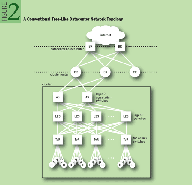
(Figure stolen
adopted from ACM article by Abts and Felderman, A Guided tour of Data-Center
Networking, 6/2012.)
Notice the three layers of
switches. The idea is to have multiple paths between the ToR and the AS
switches, so congestion and packet drops are minimized. This design dates to
1950’s AT&T Bell Labs researcher Charles Clos, and is known as a Clos
network. This is needed because each host might be sending at 1 Gbps, the
various switches might max out at 10 Gbps; if there aren’t enough paths for
packets, some get blocked/dropped. This was used back then for
electro-mechanical crossbar switches. The pattern of links looked like
woven cloth, and this is possibly why the data plane in switches is called the
switch fabric. (From a 2014 article in NetworkWorld.)
Determine
physical design:
Locate MDF, IDFs, VLAN and switch
placements, media types, etc.
Chose
hardware:
Servers, RAID, switches (or hubs),
cabling (today 100 mbps is common), routers, firewalls. Chose software (Linux,
proFTPd, ...)
To meet uptime requirements you must
carefully pick the proper equipment. Two important values that can be measured
and reported are MTBF (mean time between failures) and MTTR
(mean time to repair). These values are usually expressed in hours.
For a single component you can compute the availability as: availability =
MTBF/(MTBF+MTTR). So if the MTTR is 8 hours and a switch or router has MTBF
rating of 100,000, the availability is 99.992%. To estimate availability for a
network means combining the single component availabilities.
Single points of failure reduce
availability, multiple paths increase it: Suppose network devices “A” each
have 99% availability and “B” has 90%. Then:
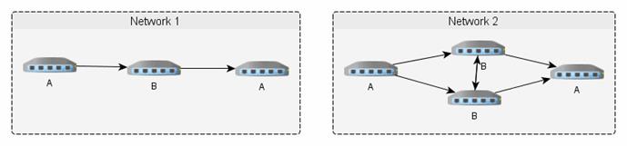
Here, network 1 has 99% * 90% * 99% =
88% availability. However, network 2 has 99% * (90% + (90%*10%)) * 99% =
97% availability. (But you must trust the manufacturer’s numbers; sometimes
you can find confirmation of those numbers on the web, but be wary of fake
reports by the vendor—or a competitor.) If a cable is cut by a farmer, there
may not be much you can do.
Allocate responsibility:
Web administrator, Network
administrator, server and workstation administration, email, ... Policy
documents should be written and used. Plan for network security monitoring,
security audits.
Comparison of Media
|
Media
|
Cost
|
Ease of Install
|
Capacity
|
Attenuation (Range in meters)
|
EMI/
Eavesdropping Susceptibility
|
|
UTP
|
very
low
|
very
easy
|
100
Mbps
|
high
(100s)
|
high
|
|
STP
|
medium
|
easy
|
155
Mbps
|
high
(100s)
|
medium
to high
|
|
Coax
|
low
to medium
|
easy
|
1
Gbps
|
medium
(kilometers)
|
medium
|
|
Fiber
|
medium
to hi
|
hard
|
2
Gbps
|
low
(10s of kilometers)
|
low
|
|
Low
power wireless
|
medium
|
easy
|
10
Mbps
|
high
|
very
high
|
|
high
power wireless
|
medium
to hi
|
hard
|
10
Mbps
|
low
|
very
high
|
|
Spread
spectrum radio
|
medium
to hi
|
medium
|
6
Mbps
|
high
|
medium
|
|
Terrestrial
microwave
|
medium
to hi
|
hard
|
10
Mbps
|
varies
|
high
|
|
Satellite
Microwave
|
high
|
very
hard
|
10
Mbps
|
varies
|
high
|
|
P2P
Infrared
|
low
to medium
|
medium
|
16
Mbps
|
varies
|
medium
|
|
Broadcast
Infrared
|
low
|
simple
|
<1
Mbps
|
high
|
high
|
NAT
Network Address Translation
(a.k.a. IP Masquerading, PAT, SNAT, DNAT) refers to a common IPV4 technique of
translating source IP/port numbers to different ones. The NAT router reverses
the translation for the reply packets. Using NAT allows one to use a large
(private) address space, who’s addresses get mapped to one or more legal
addresses (usually the router’s). NAT can help to merge to ASs (Autonomous
System). NAT causes problems while solving others. IPv6 shouldn’t
need NAT.
Lecture 10 — IPv6
Many ISP and network equipment and
service vendors make a living selling products and services to make up for the
deficiencies in IPv4. The major problems with IPv4 include a shortage of
usable addresses and security issues. (As of 12/2010, there are only 496
million IPv4 address left!)
The last of the
IPv4 address blocks was given out on 2/4/2011. There are none left.
Of course, running out of address blocks to give to RARs (and then to ISPs) is
different from running out of addresses. Some studies indicate that most
address blocks only use about 14% of their addresses.
The next version of IP, IPv6 (IP
protocol 5 is already assigned to the SIP protocol) (originally called IPng)
address these problems by completely changing the addressing scheme, routing
scheme, and adding IPSec for security. (IPSec is available as an add-on for
IPv4.)
Both IPv4 and IPv6 are used today.
Since few ISPs provide IPv6 connectivity to clients yet, it is usual to tunnel
IPv6 packets across the IPv4 Internet, to reach one of several publicly
accessible IPv4 – IPv6 gateways. Initially there was an “official” tunnel
broker to ease transitions, but that has been turned off and now you must find
commercial brokers; some of these provide free service (FreeNet6,
6gate.com, Hurricane Electric
or SixXs).
In order to help with adoption of IPv6,
the Internet Society promoted “World IPv6 Day” for June 6, 2011. 69 major ISPs
and content providers participated, by turning on IPv6 for 24 hours. There
were surprisingly few problems; however, there wasn’t a lot of traffic from
users either.
One year later, 6/6/2012 (World IP
Launch Day), IPv6
was turned on permanently by many ISPs and content providers, over
3,000. There are logos you can put on your website to show your support. In
addition, routers and switches can be certified as fully supporting IPv6. You
can see the adoption of IPv6 by examining Google’s IPv6 statistics,
or Akamai’s
statistics. (Akamai is the largest CDN (content delivery network)
operator in the world.) Currently (2015), Google reports about 7% of its users
are on IPv6. Based on that, they estimate U.S. IPv6 adoption at 21% (See Google’s
per-country adoption charts).
Comcast, which began
home IPv6 in 2011, says it implements support for home routers. Such routers
will be able to request a range of IPv6 addresses through “DHCPv6 prefix
delegation”, and then configure that range of addresses on their LAN interface(s),
and give out addresses through DHCPv6.
On your host computer, an interface configured
to tunnel IPv6 traffic via IPv4 to some gateway appears as a separate
interface. On Linux these are called sit0,
sit1, ... (Simple Internet
Transition).
Is there anything
users have to do to enable IPv6? You have 3 options:
1) Wait until your
ISP provides it
2) Enable Teredo
in Windows, if off (Miredo in Linux)
3) Use a free tunnel,
e.g. from tunnelbroker.com
(There are
circumstances where 2 and 3 do not work, if you have very restrictive firewalls
or multiple-layer NAT. See a list of IPv6
tunnel brokers on Wikipedia.)
IPv4 to IPv6
Transition Issues
[ Adapted from ArsTechnica.com/business/news/2011/02/ask-ars-how-should-my-organization-approach-the-ipv6-transition.ars]
There are a number of issues to address when thinking about switching to IPv6.
No matter what you do, it will cost something, and unfortunately, not adding
IPv6 capability is unlikely to cost your organization, for many years to come.
(The main reason why IPv6 adoption is so slow.)
First of all, IPv6 users to your site
will likely be low to start with, so it may be possible to simply enable an
IPv6 gateway to your existing IPv4 network, rather than add a new IPv6 version
alongside of (or as a replacement of) your IPV4 network. Regardless, you need
to consider these issues:
·
Your network provider is either where your servers are collocated
or hosted. If you’re collocating or leasing equipment in someone else’s
datacenter, they’ve probably already worked out the logistics of providing IPv6
connectivity to their customers (you). You can generally find out what level
they support by poking around on their website. If not, a quick email to your
support contact or opening a ticket should suffice.
·
Your networking equipment that lives between your servers
and your network provider will need to be checked out to make sure it can
support IPv6. This includes firewalls, load-balancers, proxies and caches, and
routers. (Home cable modems require “DOCSIS 3.0” or higher.)
·
Your servers’ operating systems must have IPv6 support (all
modern ones do) and that support is enabled.
·
Software networking applications will need to be check to
make sure all your configuration settings and tweaks still work the way you
thought they did before rolling the update out to production. (You can find a list
of IPv6 compatible applications on Wikipedia.)
·
Applications must be examined and updated if necessary. You’ll
need to look at all your homegrown code, your third-party products, and any
home-grown plugins and glue code that ties all this together. For example, you
might have a front-end framework that “templates out” the web site. You may have
a CMS (e.g., Moveable Type) that authors and editors spend most of their day
in. Discussion boards and forums and also commenting systems and user database
systems may need to store IPv6 addresses when before they only stored IPv4 ones.
The key to any IPv6 transition will be determining where and how your
applications deal with IP addresses at all.
·
Tunnels
With a tunnel, an IPv6 packet (headers
and all) is put inside an IPv4 packet, so it can be forwarded by existing IPv4
routers until it reaches an IPv6-capable router again. At the endpoint of such
a tunnel, the payload is now considered an arriving packet, so the IPv6 headers
are examined.
There are several tunneling
mechanisms out there, and a given system might be configured to try
one or more of them when it sees IPv6 packets. Some tunneling technologies
include “6to4”, designed for tunnels across the public Internet; “ISATAP”,
designed for within an enterprise’s internet; “Teredo”, a tunnel designed to
work across NAT routers (other tunnels may not work with NAT).
Other tunnel technologies include Linux
IPIP (IPv4 within another IPv4 packet), GRE (IPv* within IPv4, and can handle
multicast and is usual default), SIT (IPv6 within IPv4), as well as SSL (TLS)
tunnels and SSH tunnels that provide encryption for IPv4.
What if the network at the other end
only understands IPv6 while your ISP only supports IPv4? In such cases, you
can use a tunnel broker, a packet forwarding service that
connects IPv4 tunnels to the IPv6 Internet. (See above.)
Windows 7 has IPv6
turned on out of the box, and will try to use the “6to4” or “Teredo” tunneling
mechanisms to talk to the IPv6 Internet if they can’t find a local IPv6 router.
However, these tunneled packets are sometimes filtered by a firewall. Then
the system thinks it has IPv6, but it won’t work.
If you’re running a Web server or
another type of server, you will have IPv6 users who make use of NAT64
and DNS64, a system for translating between IPv6 and IPv4. There
are two things NAT64 doesn’t handle well: literal IPv4 address in URLs and
small MTUs.
For systems that have IPv4, a link such
as “http://83.149.65.1/runningipv6/what-is-my-ipv6-address.php”
works just as well as “http://www.runningipv6.net/what-is-my-ipv6-address.php”.
But the first link has an IPv4 address in the URL, which bypasses the DNS (and
DNS64 that would allow NAT64 to translate between IPv6 and IPv4.) So, avoid
literal IP addresses in URLs.
The IPv6 specifications require that
IPv6 systems support a maximum packet size (MTU) of no smaller than 1280 bytes,
while IPv4 in theory supports maximum sizes as small as 68 bytes (68 as a max
is never used, but less than 800 is sometimes used if not using Ethernet on a
data link). Since packets won’t be fragmented (split) to smaller sized
packets, they will be rejected (similar to what happens when the IPv4 “do not
fragment” flag is on).
One way to deal with the transition
between IPv4 and IPv6 is through a dual stack (having both IPv4 and IPv6)
proxy. With a dual stack Web proxy, even ancient Windows 95 machines can reach
IPv6-only content. More importantly, IPv6-only systems can reach content
hosted on IPv4-only servers. However, this solution requires applications that
can work with a proxy server. (Fortunately, all web browsers can.)
Finally, note that as ISP can’t obtain
any new IPv4 addresses (projected to happen in North America by 2015), the ISPs
are likely to resort to NAT, having multiple customers share the same IPv4
address. That may affect peer-to-peer applications, that typically can’t work
through multiple layers of (or any) NAT.
IPv6 Packet
Size (MTU)
The minimum MTU (maximum
transmission unit) that links are required to handle under IPv4 is 576
bytes. In IPv6, all links must handle a datagram size of at least 1280 bytes,
and the minimum recommended MTU is 1500 bytes.
In IPv4, packets may be fragmented at
any point: at the source or in transit by routers forwarding those packets. In
IPv6, only the source may fragment packets. The result of this requirement
is that the packet source must use ICMPv6 to determine the PMTU (path MTU,
the minimum MTU value along the path taken by packets) prior to sending traffic
and perform fragmentation where needed. These ICMP packet types must not be
filtered by any firewalls.
Certain sites won’t
report MTU correctly, and the usual value of 1500 may be too high, causing
packet loss. The web server at www.nist.gov
suffered from this problem on world IPv6 day (June 8 2011).
IPv6 Addresses
(See RFC-4291.) These are 16 bytes
(128 bits), eight groups (or “blocks”) of 4 hex digits separated by “:”. A
single contiguous group of all-zero blocks can be omitted, and leading zeros
per block too. Here’s an example:
1080::8:800:200C:417A
::1 localhost
An IPv6 address includes a network
portion and a host portion. The network portion (like IPv4) is the leading
part, known as the prefix, and a mask is used much like CIDR,
called the prefix length. Since most address prefix lengths are known
in advance, you rarely need this. For example, all regular Unicast
addresses use the last 64 bits for the host ID. (That is, the prefix is
always /64.) However, routers need to know how many bits of some address are
associated with a particular route, so they use and store the correct
information in their routing tables.
The /64 prefix has an
interesting effect on scanning a network to find hosts. Someone could attempt
to scan your whole network’s IP range (the way nmap
and other tools do for IPv4 today), but with a /64 prefix, this would be
impractical. A ping packet is around 64 bytes. A 1Gib connection could only
send less than 2 million packets per second. A /64 network has 264
IPs. Scanning 2 million each second would take about 150,000 years. Even if
you get a 10GiB/Sec connection, it would take 15,000 years. In practical
terms, someone must already know your IPv6 address to send a packet to your
NIC. Unless you number your interfaces “:1”, “:2”, “:3”, etc. Number them
randomly for security!
There are no classes or reserved
“broadcast” addresses, instead there are different types of IPv6
packets. The type (except for multicast) also indicates the scope of
the address, which is in indication of how far the address can be propagated.
(See below.) The types are:
·
A link local address will never pass through a router.
(Think of ARP.)
·
A site local address is similar to RFC-1918 private addresses
(e.g. 10.0.0.0).
·
A unique local address is similar to site local, but tries
to ensure such addresses are globally unique in case two LANs are merged. See
RFC-4193.
·
A global address is how the world knows your NIC.
·
A multicast address is like pay-per-view: only those who
subscribe to that address can receive packets sent to that address.
The leading bits
of the address indicate the type:
001 Global
Unicast (normal) (2xxx or 3xxx)
1111 110 Unique-local
address (fcxx – fdxx) (prefix: /40)
1111 1110 10 Link-local
address (fe8x – febx)
1111 1110 11 Site-local address (fecx – fefx)
(deprecated; see RFC-3879)
1111 1111 Multicast
address (ffxx); (see below for details)
1000 0000 0000
10 Reserved for “6-to-4” router addresses
::IPv4-Address Compatible
format for IPv4 addresses (prefix: /96)
::FFFF:IPv4-Addr Mapped format
for IPv4 addresses (prefix: /96)
In addition to a
type, all IPv6 addresses have a scope. The scope limits the routability
of an address:
Node-local Limited
to host (node)
Link-local Limited
to LAN
Site-Local Limited
to AS
Global Unlimited
A typical IPv6
Address might look like this:
3ffe:ffff:01f1:0000:0000:a4ff:0ee3:9566
which is a Unicast address (starts with
“001”), so the first 64 bits are the network ID and the last 64 bits, the host
ID.
Leading zeros in each block can be
omitted, and one contiguous groups of all zero blocks can be omitted:
3ffe:ffff:1f1::a4ff:ee3:9566
Finally, other parts of the prefix have
special meaning, in that they can be assigned to regional organizations to help
manage their addresses in a hierarchical way. For example, there are fields
for TLAID, NLAID and SLAID for top‑, next‑, and site‑ level aggregation IDs. Some
example addresses:
::
unspecified address (similar in use to IPv4’s “0.0.0.0”)
::1 localhost
fe80:... link-local
unicast
fec0:... site-local
unicast
2002:c0a8:0101:5::1 Represents
a 6to4 addr of 192.168.1.1/5
(used to tunnel v4 address+mask in v6)
2001:... These are
assigned by ISPs
3ffe: ... Assigned to the
6bone (no longer used)
3fff:ffff::/32 Reserved for examples
and documentation purposes
2001:0db8::/32
Reserved for examples and documentation purposes
Stateless Autoconfiguration,
NAT6, DHCP6, and Related Issues
A given NIC may have several IPv6
addresses, with different scopes. A unicast address is set automatically when
the NIC is enabled. So in a LAN, no DHCP is needed. This is similar to
ZeroConf a.k.a. Rendezvous for IPv4; it is called Stateless
autoconfiguration.
The bottom 64 bits of an IPv6 address can
be generated from a MAC address by a simple formula: One bit is toggled, and the
bits ff:fe are added in the
middle. (In the IPv6 docs, the MAC address is called the interface
identifier for some reason.) So if the gateway router sends out the same network
ID (the upper 64 bits) when asked on the all-routers multicast channel, the
host will always configure the same IPv6 address for itself. No configuration
is required, either on the host or with a DHCP server.
When a router sends
out several address prefixes, or several routers send out different address
prefixes, hosts simply create addresses from each of those prefixes. A routers
can make the hosts connected to it renumber their IPv6 addresses, by removing
the old prefix and advertising a new one.
Alternatively, a host may generate its
IPv6 address using a random number so its MAC address remains hidden from the
rest of the Internet. Windows and Mac OS (10.7 and newer) use this type of
addresses for outgoing sessions to aid privacy. (This is explicitly allowed by
RFC-4941.)
A new one is generated every so many hours.
This stateless autoconfiguration works
well, but does have some issues. Currently with IPv4, an ISP assigns a single
IP address to your cable/whatever modem. If that is attached directly to a
single computer, everything works fine. But many people have a router at home
that does NAT, so they can have many computers use that one IP address. That
scheme won’t work with IPv6, as most ISPs won’t support NATv6. Since NAT acts
as a simple firewall to block incoming connections, users will need to make
sure their host and router firewalls filter both IPv4 and IPv6 traffic. (pf for BSD, Linux, and Solaris, does
this well; iptables for Linux doesn’t,
but most Linux systems also include separate “ip6tables”
firewall software.)
Most current cable modems and home
routers have limitations preventing IPv6 operation. To use IPv6 if/when your
ISP provide it, you will need to upgrade your cable modem to one that is
compliant with the DOCSIS 3.0
standard (most in 2016 are already DOCSIS 3.0 or 3.1), and upgrade your router
to one that can handle DHCPv6. You will still need a firewall, blocking all ports
by default, and enable something like uPNP allow the OS to open ports on
demand.
With IPv6 each NIC will end up with
several addresses. When sending packets, which address is chosen? (This was
also an issue for IPv4 hosts with multiple NICs.) IPv6 includes specific rules
for this, in RFC-6724.
DHCPv6
Stateless autoconfiguration can get an
IP address and the default router’s address, but not a hostname, DNS server, or
other network parameters. DHCPv6 is needed for this reason. The standard for
this is RFC-3315 (also RFC-4361).
An issue with DHCPv6 is a decision made
to not use MAC addresses to identify the client hosts! This is of course how
DHCPv4 works. Instead, DHCPv6 uses a DHCP Unique Identifier (or DUID).
A DUID should uniquely identify each host (including the DHCPv6 server itself),
rather than single interfaces on hosts. An advantage of DUIDs is that one can
replace NICs and the DHCPv6 server and client won’t notice the change.
However, there is a problem. They forgot about virtual machines made by
cloning, and relaying.
OS clones are likely to have identical
DUIDs. A SysAdmin would have to manually change it before bringing the host
online, or the DHCPv6 server, seeing the same DUID from different hosts, will
assume all those requests are coming from a single host! You could end up with
multiple hosts with the same IP or name. On my home PC (Windows), I can see
this info:
Physical Address. . . . . . . . . :
34-17-EB-9F-21-79
DHCPv6 Client DUID. . . . . : 00-01-00-01-1B-17-2F-8C-34-17-EB-9F-21-79
This isn’t really a problem if the
DHCPv6 server is attached to the same LAN (same data link) as the client, since
it can also see the MAC address in that case and do something sensible. But
usually, the DHCP servers are in a different LAN, and the router(s) are
configured to relay DHCP traffic; in this case, the server cannot see the MAC
address of the client.
To work around this issue, some servers
deliberately operate in a non-compliant manner. It would be nice if VMware,
VirtualBox, etc. all were updated to generate unique DUIDs during a clone, but
they don’t currently (2016) do so. One possible way is RFC-6936,
which adds an extension field to the DHCPv6 request that contains the client’s
MAC address.
How to change the DUID varies with the
DHCP client software used. Typically, it uses some information such as the
host ID number from /etc/machine-id).
The DUID generated by NetworkManager is stored as a line in a DHCP lease file,
usually either /var/lib/dhclient/dhclient6.leases
or /var/lib/NetworkManager/dhclient6-*.lease.
You can use the script wide_mkduid.pl to
generate a new DUID that you can store in the appropriate file. (This
procedure is likely to change with each new release.) If not using
NetworkManager, you can configure dhcp6.conf with the DUID as the option “dhcp6.client-id”. If using the common
(2016) Dibbler DHCPv6 software, look for the file client-duid. FYI, in Windows the DUID is stored in the
registry and shown with ipconfig/all.
Anycast
An anycast address is an address
that is assigned to more than one interface (typically belonging to different
nodes), with the property that a packet sent to an anycast address is routed to
the “nearest” interface having that address, according to the routing
protocols’ measure of distance. Anycast addresses are used to cover things
like nearest DNS server, nearest DHCP server, or similar dynamic groups.
Anycast addresses are allocated from
the unicast address space, using any of the defined unicast address formats.
Thus, anycast addresses are syntactically indistinguishable from unicast
addresses. When a unicast address is assigned to more than one interface, thus
turning it into an anycast address, the nodes to which the address is assigned
must be explicitly configured to know that it is an anycast address.
A good example of
anycast is Google Public DNS, which is a large set of caching DNS
servers placed around the world. Even though the number of caching DNS servers
is high, only two addresses are used: 8.8.8.8 and 8.8.4.4. The routing system uses
anycast to deliver packets addressed to either address to the closest Google
Public DNS location.
IPv6
Multicast
These addresses
look like this (leading 4 bytes): ffxy:...
where x is the flags and y is the scope. (This is
necessary since the scope of a multicast address is not inherent in its type;
that is, you can have host, local, AS, or global multicast.)
ff
flags scope : group identifier
Where “flags” is a hex zero for a
well-known, IANA assigned multicast address or hex one for local-defined
multicast, and “scope” is one of the following:
ff01::type gid node
local (the host attached to the NIC)
ff02::type gid link
local (the data-link, or LAN)
ff05::type gid site
local
ff08::type gid organization
(AS) local
ff0e::type gid global
The gid identifies the group
(the station identification) of the multicast. A (growing) number of these are
defined (see RFC-4291). A few are:
All Nodes Addresses: The
following multicast addresses identify the group of all IPv6 nodes, within
scope 1 (interface-local) or scope 2 (link-local).
FF01::1
FF02::1 (think Ethernet broadcast)
All Routers
Addresses: The following multicast addresses identify the group of all IPv6
routers, within scope 1 (interface-local), 2 (link-local), or 5 (site-local):
FF01::2
FF02::2
FF05::2
Every IPv6 host must listen to
“station” FFxx::1, but only routers are listening to the FFxx::2
multicast address. (So a host can send a message to the router attached to its
LAN, using FF02::2. The computer could use that to ask routers for their IPv6
addresses, and use one as its default gateway; no DHCP needed!)
So if the “NTP servers group” is
assigned a permanent multicast address with a group ID of 0101 (hex), then:
FF01::101 means all NTP servers on the
same interface (i.e., the same node) as the sender.
FF02::101 means all NTP servers on the same link as the sender.
FF05::101 means all NTP servers in the same site as the sender.
FF0E::101 means all NTP servers in the Internet.
Multicast Listener Discovery
(MLD) is a set of three ICMPv6 messages equivalent to version 2 of the Internet
Group Management Protocol (IGMP) for IPv4, used to manage subnet multicast
membership. Instead of using IGMP, IPv6 uses ICMPv6 messages for the same
functionality, now called MLD. MLD is the protocol that allows multicast
listeners to register for multicast addresses they want to receive.
Neighbor
Discovery (ND) Replaces ARP
The ICMPv6 neighborhood discovery
(ND) (RFC-4861) function serves
to locate link-local neighbors and is similar to the function of ARP with IPv4.
However, IPv4 has no means to detect whether a neighbor is reachable. With
IPv6, ND locates link-local routers, identifies duplicate IPv6 addresses, and determines
the link-layer addresses for neighbors known to reside on attached links (and
to quickly purge cached values that become invalid). It does all that while
eliminating the link-local broadcast traffic generated by ARP. This
substantially improves packet delivery in case of failed routers or link
interfaces that changed their link-layer address, and solves the problem of
outdated ARP caches.
In addition, ND is used to discover automatically
routers, network prefixes, and other networking parameters, all without DHCP.
(Show packetlife
blog entry.)
Solicited
Node Link-Local Multicast Address
This is a special multicast address
used as destination address in ND. An example might looks like:
ff02::1:ff00:1234
The “ff02” shows this is a link-local
multicast address. The whole address is formed by appending the last 24 bits
(3 bytes) of the address (whose MAC address we want to know) to
“ff02:0:0:0:0:1:ff00::/104”. In this example, a packet should be sent to
address “fe80::1234”, but the network stack doesn’t know the current layer 2
MAC address. It replaces the upper 104 bits with the solicited node
link-local address and leaves the lower 24 bits untouched. This address is
now used “on-link”. The corresponding node should send a reply containing its
layer 2 MAC address.
Checking for
IPv6 Connectivity
You can see if your computer has working
IPv6 connectivity by connecting to www.kame.net, test-ipv6.com, or www.apnic.net. KAME
is a Japanese project that built an IPv6 networking stack for BSD and Mac OS. Their
mascot is a turtle, which dances if you connect over IPv6.
APNIC is responsible for giving out IP
addresses in the Asia-Pacific region, and their web site will tell you your IP
address (IPv4 or IPv6) in the top left corner of the page.
Internet Explorer under Windows, Safari
on Mac OS X 10.4, and Firefox on Windows, Linux, and BSD, will use IPv6 when
available on the system, but Firefox 3 on the Mac has IPv6 turned off in about:config. (Note that
if you don’t have IPv6 at home, you can disable support for that in your web
browser and gain a performance boost.)
Lecture
11 — Network Configuration
This is done only on a
running system, and must therefore be redone every reboot. Various bootup scripts
read configuration files and run the commands. So, the SA configures
networking by editing these files. This is called static network
configuration. (The other option is to run a client daemon that
obtains networking configuration data from a server, using a protocol such as
DHCP. This is called dynamic network configuration.)
There are only a few commands
that are used for static network configuration. These can be run by boot
scripts, or manually at any time to view or modify the network configuration.
The common tools are:
·
hostname which
sets the hostname (see also hostnamectl),
·
ifconfig (or
ip addr for Linux) which configures
NICs with IP address(es) and other parameters, and
·
route (or ip route on Linux) which set up a default gateway and
other routes).
·
vi /etc/resolv.conf
(but this depends on various daemons and other files, that may overwrite any
changes made manually.) Other files can be edited too, including /etc/hosts.
If using the Linux default
of NetworkManager (instead of the older “network” service), there are
additional tools and considerations. Some of the additional tools include nmcli and a GUI tool (included
with Gnome) called control-center
that has a Network tool
integrated.
Two important
points: The older ifconfig
command doesn’t know about all the parameters available in Linux, such as multiple
IPv4 addresses per NIC. Secondly, neither ifconfig
nor ip commands know all the
parameters for wireless NICs (SSID, WPA parameters, etc.). There are special
commands to manage the additional wireless NIC parameters, but you still use ifconfig or ip to manage the IP parameters.
Missing from that list of
commands are any that manage DNS information. That’s because there are none!
DNS is handled by a common library, which reads the file /etc/resolv.conf each time it is
used. DNS (for static setup) is managed solely by editing that file. (DNS is
discussed in more detail, later.)
Common networking admin
tasks include configuring networking, modifying configuration files (so the
system will be configured correctly, automatically at boot time), turning
networking on and off, and bringing interfaces up and down. (Usually, after
making changes to configuration files, you need to bring the affected interface
down, then up.)
Commands for these common
tasks include
·
systemctl start|stop
NetworkManager
·
systemctl start|stop
network
·
nmcli connection reload
·
nmcli dev disconnect interface
·
nmcli connection up interface
·
ifup/ifdown interface
Remember that after making
configuation changes, you must bring the interface down, then up. If you are
using NetworkManager and edit config files without using nmcli or the NM GUI tools, you must
also reload the configuration files.
These commands are
discussed below, at static configuration. There are of course many
other commands, for example the PPP related commands, the dynamic routing
daemons (gated or routed or quagga), and the DHCP client and server daemons.
Quagga is named
after an extinct subspecies of the African zebra. It is a fork of the GNU
Zebra project, which has been inactive since 2005.
Update
(10/26/2011): The Internet Systems Consortium (ISC) has created a project
to stabilize the code base for Quagga and offer commercial support to vendors
using the code. The initiative is called the Open Source Routing Project.
Google turned to the ISC for assistance in creating a community around Quagga
because it wants to use less expensive, highly programmable routers in its
network. (The Open Source Routing Project is sponsored by Google.) Google has
created an open source router called the Open LSR, which is a combination of
merchant switching silicon, a commodity server, the OpenFlow protocol, and the
Quagga open source code. Google plans to use Open LSR in its core network.
For a host that is
dynamically configured, the DHCP client daemon configures networking,
including: sets a default route, sets the IP addr of an interface, Sets any
proxy configuration, and usually configures the resolver (that is, configures
the IP address of a DNS server). When using static IP configurations you must
configure this stuff manually.
Solaris provides static network
setup tools (similar to what is run when installing the system; RH anaconda has
similar functionality): sysidnet
and sysidsys (?). See man sys‑unconfig.
NIC Names On
Linux
The names eth0, eth1,
etc. are assigned by the kernel in the order that the kernel creates the
Ethernet interfaces. While NICs that are detected at boot time are usually
detected in the same order every time, and are therefore assigned the same
names every time, the same is not true of NICs that are hot-plugged. These can
be detected in any order and end up getting assigned different names by the
kernel on different occasions. Since many systems use hot-plugging for all
device detection today, even at boot time, this means naming NICs (or any other
device for that matter) can be a problem. This is because the configuration
files use these names to assign IP addresses and other parameters. It would be
bad if the IP addresses of eth0
and eth1 got reversed!
Modern systems have a way to map the
devices to logical (kernel) names such as eth0,
by using various physical characteristics that differ between similar devices,
such as MAC addresses for NICs, or serial numbers (or which slot in the bus the
device uses). For Linux, this is done by some command invoked from the udev
sub-system. Debian uses ifrename
or nameif, or the map directive in /etc/network/interfaces file.
Newer (2.6) Linux systems typically use
the biosdevname utility (invoked from udev /lib/udev/rules.d/71-biosdevname.rules).
(Show “sudo biosdevname -d”.) Dell computers use
biosdevname by default; others do not. If bissdevname has already renamed your
NIC, systemd won’t rename it again. The biosdevname names are em# (ex: em0)
for embedded on the motherboard NICs, p<slot>p<ethernet port> (ex:
p2p1) for PIC NICs, and p<slot>p<ethernet port>_<virtual
interface> (ex: p2p1_3) for “virtual” NICS.
You can prevent udev from running
biosdevname to rename NICs by passing the kernel argument of biosdevname=0 to the kernel (except on Dell). Pass net.ifnames=0 as well to prevent systemd from renaming (see systemd-udevd(8)).
Or
make a custom 71-biosdevname.rules file and use whatever rules you wish to name NICs.
Here’s a sample udev rule:
SUBSYSTEM=="net",
ACTION=="add", DRIVERS=="?*", \
ATTR{address}=="00:11:22:33:44:55", ATTR{type}=="1",
\
KERNEL=="eth*", NAME="eth0"
(Use your NIC’s MAC address instead.)
RHEL 7 uses these
steps to rename a NIC:
1. A rule in
/usr/lib/udev/rules.d/60-net.rules instructs the udev helper utility,
/lib/udev/rename_device, to look into all /etc/sysconfig/network-scripts/ifcfg-*
files. If it finds an ifcfg file with a HWADDR entry matching the MAC address
of an interface, it renames the interface to the name given in the ifcfg file
by the DEVICE directive. Otherwise:
2. A rule in /usr/lib/udev/rules.d/71-biosdevname.rules
instructs biosdevname to rename the interface according to its naming policy,
provided that it was not renamed in a previous step, biosdevname is installed,
and biosdevname=0 was not given as a kernel command on the boot command line.
(biosdevname is off by default except on Dells.) Otherwise:
3. A rule in
/lib/udev/rules.d/75-net-description.rules instructs udev to fill in the
internal udev device property values ID_NET_NAME_ONBOARD, ID_NET_NAME_SLOT,
ID_NET_NAME_PATH, ID_NET_NAME_MAC by examining the network interface device.
Note, that some device properties might be undefined. This step merely gathers
information for step 4, which implements several renaming rules depending on
what information is present:
4. /usr/lib/udev/rules.d/80-net-name-slot.rules
instructs udev to rename the interface, provided that it was not renamed in
step 1 or 2, and the kernel parameter net.ifnames=0 was not given, according to
the following priority: ID_NET_NAME_ONBOARD, ID_NET_NAME_SLOT, ID_NET_NAME_PATH.
It falls through to the next in the list, if one is unset. If none of these
are set, then the interface will not be renamed. These values are used as
follows to set the name:
Scheme
1: Names incorporating Firmware or BIOS provided index numbers for on-board
devices (example: eno1), are applied if that information from the firmware or
BIOS is applicable and available, else falling back to scheme 2.
Scheme
2: Names incorporating Firmware or BIOS provided PCI Express hotplug slot index
numbers (example: ens1) are applied if that information from the firmware or
BIOS is applicable and available, else falling back to scheme 3.
Scheme
3: Names incorporating physical location of the connector of the hardware
(example: enp2s0), are applied if applicable, else falling directly back to
scheme 5 in all other cases.
Scheme
4: Names incorporating interface's MAC address (example: enx78e7d1ea46da), is
not used by default, but is available if the admin chooses.
Scheme
5: The traditional unpredictable kernel naming scheme, is used if all other
methods fail (example: eth0).
Servers often have multiple Ethernet
ports, either embedded on the motherboard, or on add-in PCI cards. Linux has
traditionally named these ports ethX, but there has been no correlation
of the ethX names to the chassis labels — the ethX names are not
guaranteed to refer to the same NIC each boot.
Starting with Fedora 15,
Ethernet ports use a new naming scheme that corresponds to physical
locations. The details don’t matter, because...
Starting with Fedora 19, the naming
scheme is altered again (see Systemd
- Predictable Network Interface Names):
1. On the
motherboard devices will be named based on the index number provided by BIOS,
for example “eno1” (Ethernet
onboard). With VMware, the index number is weird, 1679965 or some such.
2. If that isn’t
available or there are no onboard NICs, The PCI hot-plug slot number provided
by BIOS is used, for example “ens1”.
3. If neither rule
1 nor rule 2 provide the name, the system tries to name the NIC according to
its physical location, for example “enp2s0”
(PCI bus 2, slot 0).
4. If none of that
applies, the NIC is not renamed, for example “eth0”.
5. Not used by
default, but supported if enabled, NICs can be named by their MAC address, for
example “enx78e7d1ea46da”. (I
would guess this option would require setting HWADDR in each ifcfg-* config
file.)
Red Hat Enterprise
Linux 7 will indeed use systemd and all the new NIC names, as described here.
Udev can also assign an “alias” (or
“user-friendly”) name. For example, on my home Fedora 19 system, “enp2s0” has the alias “p2p1”. If an alias is defined, the
various tools use that name; however, there doesn’t seem to be any standard way
to determine this alias name (or the actual name given an alias name). The
best I came up with so far is (nmcli = NetworkManager CLI utility):
# nmcli [-t] -f DEVICES,NAME con show active
This outputs the name used by ifconfig or ip, and the “real” name (of the config file, and the DEVICE= entry therein).
On recent Fedora, the
“ip link show” command reports any aliases set.
You can also try to find the info in
the log files:
# grep -E
'eth[0-9]|em[0-9]|p[0-9]p[0-9]|en[op][0-9]|enx?' /var/log/messages
or in the systemd/udev files (generated
in a ram disk at boot):
# find /run/udev -exec grep -IE '...'
'{}' +
(Where “...” is the same ugly regex as
above.)
The original NIC name
is not only renamed by udev and/or systemd. NICs can be given alias
(“user-friendly”) names as well. This is why the name shown with ifconfig or ip link
may not match the name of the config file, /etc/sysconfig/network-scripts/ifcfg-NIC_name.
On a Fedora 19
system, the NIC shows with the name p2p1,
but the config file is named “ifcfg-enp0s3”.
Clearly an alias was assigned, but not by me. I found where udev/systemd does
that:
# cat
/run/udev/data/n2
I:319231
E:ID_BUS=pci
E:ID_MM_CANDIDATE=1
E:ID_MODEL_FROM_DATABASE=PRO/1000 MT Desktop Adapter
E:ID_MODEL_ID=0x100e
E:ID_NET_NAME_MAC=enx080027817ebb
E:ID_NET_NAME_PATH=enp0s3
E:ID_OUI_FROM_DATABASE=CADMUS COMPUTER SYSTEMS
E:ID_PCI_CLASS_FROM_DATABASE=Network controller
E:ID_PCI_SUBCLASS_FROM_DATABASE=Ethernet controller
E:ID_VENDOR_FROM_DATABASE=Intel Corporation
E:ID_VENDOR_ID=0x8086
E:SYSTEMD_ALIAS=/sys/subsystem/net/devices/p2p1
G:systemd
Exercise: Check your
system’s NIC’s name, and compare to the config file for that NIC.
By changing the naming convention,
system administrators will no longer have to guess at the ethX to
physical port mapping, or edit udev
rules on each system to rename NICs into some “sane” order. However, for
servers with no hot-plug NICs or wireless connections to worry about, I prefer
to disable this renameing.
If you do disable the new names,
make sure to fix up and rename the ifcfg-*
file(s) to match!
The current (2014) rules don’t
rename USB NICs; you need to define your own udev
rules for those (but don’t use “standard” names such as eth#, or your name may collide with another NIC’s name
set by the kernel).
This “feature”
affects all physical systems that expose network port naming information
through BIOS: SMBIOS 2.6 or later (specifically field types 9 and 41). Dell
PowerEdge 10G and newer servers (PowerEdge 1950 III family, PowerEdge R710
family, and newer), and HP ProLiant G6 servers and newer are known to expose
this information, as do some newer desktop models. Furthermore, most older
systems expose some information in the PCI IRQ Routing Table, which will be
consulted if information is not provided by SMBIOS.
Existing installations upgraded from
older Fedora systems will not see a change in names, unless the legacy /etc/udev/rules.d/70-persistent-net.rules
file is deleted, and the HWADDR
lines are removed from all /etc/sysconfig/network-scripts/ifcfg-*
files, and those files are renamed to use the new device names.
To prevent udev
and systemd from renaming NICs, you can pass some extra parameters via the
GRUB command line: “net.ifnames=0”
prevents systemd from renaming, and “biosdevname=0” prevents udev from renaming (except
for some Dell computers).
Do not forget that when
the name of the NICs change, you must change the names (and content) of your ifcfg-* files to match, as well as any
firewall rules that mention those interfaces by name (grep is your friend).
The naming rules for Fedora 22 are
found in the Fedora
22 networking guide. F22 supports five different naming schemes!
According to that (untested by me), a udev rule file named 60-net.rules takes precedence when
naming interfaces, and that it scans all ifcfg files looking for ones who’s MAC
address is listed in the HWADDR=
line. If such is found, the interface gets the name given by the DEVICE= line in that file.
NetworkManager
(Linux only)
Modern Linux distros use NetworkManager (often referred to
simply as “NM”), a tool that will automatically monitor your links (the state
of the LANs that NICs connect with) and bring up the network when the link is
detected. This works for wireless as well. NetworkManager is a daemon that
runs with root privileges to allow normal users to configure networking.
(Security is controlled via PolicyKit.) In fact, there is little a user can do
to configure or control NM; it is designed to be hands-off. The command line
tool is nmcli.
RHEL 7 will use NM
(and systemd). The networking
guide for RHEL7 includes lots of useful information. This should
apply to modern Fedora as well.
NetworkManager tries to
detect wired and then wireless connections, pick one, and configure it. It
will automatically re-connect to networks as you travel or when they go down
(and come back up later). NM works poorly with static configuration. It is
not as useful for servers. Both Fedora (and Red Hat) and Debian have modified
NM, to use their standard configuration files rather than NM’s own system.
You can disable
NetworkManager and enable the old network
service (once you’ve installed it), then restart networking (or just reboot). For
Fedora, you use “systemctl disable NetworkManager”,
and then enable the older service with “systemctl
enable network”. (chkconfig
should work for this too.) You may need to install system-config-network with yum (not certain about that).
See below (“turning off NetworkManager”) for details.
Most Linux distros
use a fixed version of NetworkManager that will work for static IPs. It uses
the older distro-specific configuration files, so there is little need to
switch to the older service. (See bugzilla.redhat.com/show_bug.cgi?id=698199.)
However, NM doesn’t use the network-scripts, doesn’t use standard dhclient configuration files for DHCP
(as of Fedora 20), and doesn’t use the ifcfg-iface-range*
or the ifcfg-iface:number (alias or clone) files. Oddly, there
is some documentation describing ifcfg-iface-user files; NetworkManager
might use that.
A GUI helper tool called nm-applet runs as an applet (a widget)
docked into your system tray. This will notify the user of link state changes,
prompt the user for passwords for VPNs (and stores them). The idea is to make
network configuration trivial and not require deep knowledge or the root
password. It is especially useful for managing wireless networking.
There are other tools you
can use; most start with “nm”.
In particular, you can use the nm-tool
to view and nm-connection-editor
(GUI) utility to edit your ifcfg-*
configuration files.
NetworkManager won’t
know about changes made to configuration files except if edited using the NM
tools. If you edit config files directly, you will need to reload connections.
Even then, changes to
config files only occur when the interface in question is brought up (online).
Thus, after making changes, you need to being the interface down, then up.
To see boot messages
related to NM on Linux with systemd, use the command:
journalctl -b _SYSTEMD_UNIT=NetworkManager.service
The nm-applet tool uses the per-user GConf database (originally a Gnome
feature, but often used for KDE and other environments too) to store networking
configuration data, under ~/.gconf/.
As a consequence of this, a host that allows multiple users to log in with
GUIs will have trouble as the second user will mess up the configuration for
the first user. Also, the GConfd
daemon is rarely started unless the GUI is running, so when booting to
run-level 3 (or in more modern terms, when you don’t start the GUI) NM can’t
get configuration data.
There are a number of
tools to manage GConf: the gconf-editor
GUI tool and the gconftool-2
command line tool are commonly used.
As of Fedora 15,
gconf has been “superceeded” with “dconf”. What will be used in future
versions, dconf or gconf, or both together, no one can say.
NM is user-centric; the
networking is configured when a user logs in, so NM won’t run until someone
logs in. It allows per-user network connections to be defined. You need to
configure networking so the network comes up at boot time. But, if you then
log in (to the GUI) to troubleshoot networking, NM may change the current
configuration to the one defined for that use. This can make troubleshooting
difficult.
NM uses udev to find NICs
(which remembers them and names them by their MAC addresses). Udev then
“publishes” notices about them using the D-bus communication service (IPC). Which
processes can receive these notices is controlled by the desktop security subsystem,
PolicyKit. So besides using nm-applet/GConf,
NM can be affected by Dbus (and HAL) and udev configuration, which may be
managed using other tools, e.g., the KDE control-panel. However, such changes
may not get stored back into ~/.gconf
files, and can be lost after a user logs out. Worse, if you use different
tools to configure networking, it is unclear which one “wins”.
NM is designed for laptops
with one NIC. If multiple NICs of the same type (e.g. wireless) are present,
NM can’t store different configurations for each; the last one configured
“wins”. It is expected that NM will evolve and such issues will be solved.
NetworkManager can be disabled on most
servers or wired hosts, and these configured “old-school” using the standard ifconfig, hostname, and route
tools (or for Linux, the newer ip
tool). If you do turn off NM, remember to turn on the old network service. Remember, as of
2012, on Red Hat systems NM will use the older config files, so you probably
don’t need to turn it off. I would however avoid using GUI or other tools to
configure networking, and instead just edit the various files.
The main configuration file
used is /etc/NetworkManager/NetworkManager.conf.
This is an “ini” configuration file, with section names in square brackets and
each section containing name=value settings. The specs for this file
can be found at live.gnome.org/NetworkManagerConfigurationSpecification.
An admin guide can be found at wiki.gnome.org/NetworkManager/SystemSettings.
Another one is available at www.arachnoid.com/linux/NetworkManager/.
By default, only a main section is needed. It contains a
plugins directive which says
which configuration files should be used for NICs and persistent connections:
the internal NM config (“keyfile”),
the Ubuntu config (?), or the standard Red Hat config files, /etc/sysconfig/network-scripts/ifcfg-name_of_nic
(“ifcfg-rh”). More than one
plugin can be specified. A sample file might look like this:
[main]
plugins=ifcfg-rh,keyfile
When using NM’s keyfile
plugin, the configuration data is in ini-style files under /etc/NetworkManager/system-connections/.
A sample for a single wired NIC might look like this:
[connection]
id=Auto eth0
uuid=27afa607-ee36-43f0-b8c3-9d245cdc4bb3
type=802-3-ethernet
autoconnect=true
timestamp=0
[ipv4]
method=auto
[802-3-ethernet]
mac-address=0:23:5a:47:1f:71
NM is supposed to be
able to read the standard network config files under /etc/sysconfig, but may not support all the features of
the older network service.
When NetworkManager brings
up a network connection, it runs the scripts that are stored in /etc/NetworkManager/dispatcher.d, in
alphabetical order (so the scripts start with a number, e.g. “05-foo”). This feature can be used to
notify automatically users of network connections, mount NFS or SMB shares,
start servers, etc.
NetworkManager sets a hostname
from /etc/sysconfig/network’s HOSTNAME variable.
This is only true on
more recent Linux NM/systemd systems, if the file /etc/hostname isn’t present.
NetworkManager doesn’t use the
standard dhclient.conf file.
This is a widely reported bug. Instead, it builds a new file dynamically for
each interface, /var/run/nm-dhclient-interface.conf
or /var/lib/NetworkManager/dhclient-interface.conf,
depending on the version, which it then calls as the config file for dhclient (and then deletes). Since
this file is generated every time, you can’t edit it. (You can see this from a
ps listing, if dhclient is running.)
On Fedora, NM looks for /etc/dhclient-<interface>.conf
then /etc/dhcp/dhclient-<interface>.conf
and will merge the first found into the dhclient
config files it produces dynamically. Notice it doesn’t look for the
system-wide dhclient.conf file.
This often results in resolv.conf
not showing the proper nameserver IPs or domain name, when using ifcfg-rh. There
are two fixes available:
1. NM will pay
attention to directives in the ifcfg
files. Static nameservers and the default domain (the “search” directive from
/etc/resolv.conf) can be set in each NIC’s ifcfg file:
DNS1=4.2.2.1
DNS2=4.2.2.2
DOMAIN="example.com" # Can list up to six
This will ensure that the
nameservers are correct every time for static IP configurations. (See /usr/share/doc/init*/sysconfig.txt for
a description of the directives that can be used.) However, not all dhclient options can be set using this
method.
2. Make a symlink
from /etc/dhcp/dhclient-interface.conf
to dhclient.conf. Do that for
each interface.
3. (Not
recommended: if using ext4, you can use chattr
to set the resolv.conf as
immutable.)
NetworkManager does
run the scripts in /etc/dhcp/dhclient.d/,
just like dhclient-script
would. See the /etc/NetworkManager/dispatcher.d/*dhclient
script.
Turning
Off NetworkManager:
If you want to use the
standard (“legacy”) network service, i.e. not using NetworkManager (which isn’t
really needed if you’re on a wire and the config never changes) you can remove
NetworkManager or stop and disable it, then use system-config-network (yum install
system-config-network) to
configure your network. (Or, just hand-edit the config files.)
You can then bring up your
NICs with “systemctl start network”,
or use “service network start”
which will get rerouted to the new systemd. You bring them down similarly, or
use restart after editing the
config files. (The NetworkManager equivalent command to restart networking is
“nmcli connection reload”, or just “nmcli c r”.) To have networking start at
boot time, you need to enable network.service.
There is no actual network.service unit file with
systemd. Instead, systemctl,
when it doesn’t find a unit file for network.service,
will try to run /etc/init.d/network,
and the result is a “fake” network.service.
You can see this if you turn on network
and then use systemctl status network.service.
There is no Fedora package
to install with yum to get the
old network shell scripts. You have them already, as they are included with
the standard (core) yum package initscripts.
Summary of steps to turn
off NM:
systemctl stop NetworkManager.service
systemctl disable NetworkManager.service
systemctl enable network.service
systemctl start network.service
Network
Interface Config Files
All configuration is stored
in various files. The names of the files and their syntax varikous according
to your system type and specific distribution and version. Here, we will
concentrait on Red Hat (Fedora) network config files.
Some configuration files,
such as /etc/hosts, /etc/hostname, /etc/resolv.conf, /etc/nsswitch.conf,
and others apply to nearly every *nix system.
On RH, per-interface
configuration files go in /etc/sysconfig/network-scripts/ifcfg-name,
where the suffix name
refers to the name of the device that the configuration file controls. By convention,
the ifcfg file’s suffix is the same as the string given by the DEVICE directive in the configuration
file itself. (Some versions of Fedora at least depend on that.) System-wide
settings go in /etc/sysconfig/network.
Note that a setting in the ifcfg file will override the same system-wide
setting, for that interface.
As with all RH config
files under /etc/sysconfig, you
can find documentation for each file in /usr/share/doc/initscripts/sysconfig.txt.
A sample ifcfg-eth0 file might look like this:
DEVICE=eth0
BOOTPROTO=none|dhcp
ONBOOT=yes
PREFIX=24
IPADDR=10.0.1.27
To enable a normal user to
set the interface up or down, add “USERCTL=yes”.
If you add “HWADDR=MAC_address”,
it should cause the interface to be named by the DEVICE=
entry, regardless of the file’s name or other network settings.
If using DHCP, you can add
additional entries to control the configuration: Add “PEERDNS=no” to prevent DHCP from
updating /etc/resolv.conf. If
using PEERDNS=no, you can also
add entries such as “DNS[123]=ip-address”
and “SEARCH="gcaw.org
hccfl.edu"” to update resolv.conf
with that information instead of the DHCP server supplied data.
Configure
IP with client-side DHCP
DHCP (dynamic host
control protocol) is related to RARP and BOOTP protocols, all of which send out
a special broadcast packet containing a MAC address. The response contains
networking configuration information, such as:
·
IP address and mask of NIC
·
Gateway IP address to use (Used to set default route)
·
IP address of DNS servers
·
Other information (hostname, default domain name, ...)
There are many DHCP clients available
and different systems use different ones (e.g., pump,
ISC’s dhcpcd and dhclient). In essence, they all work
the same way: When a NIC is to be brought up and is marked to be configured
via DHCP, the DCHP client is run which sends out the broadcast and listens for
the response.
These clients are usually configurable,
to allow you to over-ride any configuration information received. The standard
Linux client is dhclient, which
uses the config file /etc/dhcp/dhclient.conf
(which doesn’t exist by default, but has a good man page with examples). Since
bringing up or shutting down NICs may require extra steps, dhclient will also run the command dhclient-script, which in turn runs
the shell scripts (if any) in /etc/dhcp/dhclient.d.
Anytime the system’s primary interface
changes, such as by PPP, wireless, etc., causes the DHCP client to run again (as
does a lease expiring). When run, a DHCP client will replace /etc/resolv.conf.
When shutting down,
it restores the previous resolv.conf,
so be sure to stop dhclient
daemon before editing that file, when making a static setup.
Demonstrate: make sure eth0 set to DHCP, not static, and dhclient*.conf are renamed or don’t
exist. Then: release DHCP data, bring up interface, and run dhclient while capturing packets:
dhclient
-r eth0; ifconfig eth0 up #no IP
addr yet.
# start capture of eth0 with wireshark
dhclient eth0
# stop capture
Show /etc/dhcp/dhclient*.conf. (Solaris: /etc/default/dhcpagent) man dhclient, dhclient.conf. Use to set hostname, default domain, ...:
interface
"eth0" {
supersede host-name "whoopie.gcaw.org";
prepend domain-name-servers 0.0.0.0;
prepend domain-name "hccfl.edu ";
}
The search (or domain) keyword of a system’s resolv.conf file can be overridden on a per-process basis
by setting the environment variable “LOCALDOMAIN”
to a space-separated list of search domains. See resolv.conf(5) for details. Note the domain-name lines
can list multiple domain names (e.g., ... "foo",
"bar";).
NetworkManager doesn’t use
dhclient’s standard config file, but rather some generated file.
To set up Solaris 10 for DHCP: touch /etc/hostname.iface.
This makes the system plumb the iface interface when booting. Next,
create /etc/dhcp.iface.
This file can be empty but can contain two directives: “primary” to indicate this is the system’s primary NIC
when you have more than one, and “wait seconds” to change the default
time of 30 seconds to wait for the DHCP server to respond. If DHCP doesn’t set
a correct hostname (or any hostname) just make sure the file /etc/nodename contains the correct
FQDN for your system’s primary interface.
Configuring
IP using Zeroconf (a.k.a. Rendezvous) [Adopted from zeroconf.org]
Zero configuration
networking means making it possible to take two computers, connect them
with a crossover Ethernet cable, and have them communicate usefully using IP
without needing any sys admin to set it all up for you. Zeroconf is not
limited to networks with just two hosts. Now that it’s common for computers to
have IEEE 802.11 (wireless) networking built-in, you don’t even need cables.
Historically, AppleTalk
handled this very well. On Windows PCs, Microsoft NETBIOS and Novell IPX
provided similar ease-of-use on small networks. But Apple wanted an all-IP
version, to be used for iPod for example. This version is called Rendezvous,
and then version 2 was renamed to Bonjour. Apple has released Bonjour
under the Apache open source license.
A Linux implementation of
zeroconf can be seen in dmesg
output with the name “IPv4LL”.
Zeroconf uses IP
addresses of 169.254/16
for link-local addresses that can be automatically assigned. No DHCP
server or static IP address should use this range (RFC-3927).
When a host wishes to
configure an IPv4 Link-Local address, it selects an address using a
pseudo-random number generator with a uniform distribution in the range from 169.254.1.0 to 169.254.254.255 inclusive. The IPv4 prefix 169.254/16 is registered with the IANA
for this purpose.
The first 256 and last 256
addresses in the 169.254/16
prefix are reserved for future use and MUST NOT be selected by a host using
this dynamic configuration mechanism. The pseudo-random number generation
algorithm MUST be chosen so that different hosts do not generate the same
sequence of numbers.
After it has selected an
IPv4 Link-Local address, a host MUST test to see if the IPv4 Link-Local address
is already in use before beginning to use it. A host probes to see if an
address is already in use by broadcasting an ARP Request for the desired
address.
[Details: The client MUST
fill in the “sender hardware address” field of the ARP Request with the
hardware address of the interface through which it is sending the packet. The
“sender IP address” field MUST be set to all zeros, to avoid polluting ARP
caches in other hosts on the same link in the case where the address turns out
to be already in use by another host. The “target hardware address” field is
ignored and SHOULD be set to all zeros. The “target IP address” field MUST be
set to the address being probed. An ARP Request constructed this way with an
all-zero “sender IP address” is referred to as an “ARP Probe”.
Having probed to determine
a unique address to use, the host MUST then announce its claimed address by
broadcasting ANNOUNCE_NUM ARP announcements, spaced ANNOUNCE_INTERVAL seconds
apart. An ARP announcement is identical to the ARP Probe described above,
except that now the sender and target IP addresses are both set to the host's
newly selected IPv4 address. ]
At any time, if a host
receives an ARP packet (request or reply) on an interface where the
'sender IP address' is the IP address the host has configured for that
interface, but the 'sender hardware address' does not match the hardware
address of that interface, then this is a conflicting ARP packet, indicating an
address conflict. A host MUST respond to a conflicting ARP packet. ...
Multicast DNS (mDNS)
provides the ability to do DNS-like operations on the local link in the absence
of any conventional unicast DNS server. mDNS allows a network device to
choose a domain name in the “.local” namespace and announce it using a special
multicast IP address.
In addition, mDNS
designates a portion of the DNS namespace to be free for local use, without the
need to pay any annual fee, and without the need to set up delegations or
otherwise configure a conventional DNS server to answer for those names. The
DNS top-level domain “.local.”
may be designated a special domain with special semantics, namely that any
fully-qualified name ending in “.local.”
is link-local, and names within this domain are meaningful only on the link
where they originate.
nss-mdns is a plugin for the GNU Name Service Switch
(NSS), providing host name resolution via Multicast DNS (aka Zeroconf),
effectively allowing name resolution by common Unix/Linux programs in the
ad-hoc mDNS domain .local.
DNS-SD allows for
service discovery by using mDNS and adding some special TXT records to the DNS
DB (the mDNSresponder service).
None of the zeroconf
protocols are currently standardized by anyone. In addition Microsoft has competing
standards to the widely used Bonjour. Some current and popular implementations
include: Bonjour, Howl (from Porchdog software, not being maintained anymore),
Avahi (for BSD and Linux systems, and LLMNR for MS (Ships with WinCE 5.0).
Configuring
Static IP (for servers)
Static IP: Have
boot-up scripts run ifconfig.
Also must add default gateway with route
(or be running a routing daemon). The hostname is set with the hostname command (Not the FQDN!).
The DNS domain name is set
in /etc/hosts by having an entry
with both the FQDN and the (short) hostname. (Solaris: /etc/defaultdomain.) You can run the command anytime but
the resulting configuration is lost at the next boot. To make a permanent
change, the commands are automatically run by the boot scripts. Actually on
modern systems the scripts already run the correct commands (for common setups
only!), and the actual parameters are stored in various configuration files
that differ from one Unix/Linux system to the next.
In the old days, you edited
the boot rc scripts by hand to add the commands. Today, you edit some files
containing the parameters to these commands, such as /etc/sysconfig/network. (This change was made to support
GUI and cmd-line programs that edit this info.) Which files to edit is
discussed below.
Configure
interfaces:
ifconfig
eth0 10.41.234.234 netmask 255.255.0.0 \
broadcast 172.16.255.255
Modern Linux uses “ip addr”
commands; see ip-address(8), or
run “ip addr help”.
The equivalent for the above would be:
ip addr add dev eth0 address 10.41.234.234/16
Note that the ip link show
command will report NIC aliases!
If necessary, you can set layer 2 (Ethernet)
parameters on a NIC, using:
mii-tool
(detects NIC type, protocols, config. Use “-v”
option for details. This is a Linux-only command.)
ethtool [single-option] interface
— some query options: ‑a, ‑c , ‑g,
‑i, ‑d, ‑e,
‑k, and ‑S. (Ethtool is available on Unix
and Linux.)
Suppose some NIC
isn’t talking to its switch. Maybe the problem is with auto-negotiation:
ifdown eth0
ethtool -s eth0 \
autoneg off [speed 100 duplex full ...]
ifup eth0
Which NIC is bad?
This causes the NIC’s LEDs to blink, so you can find it:
ethtool -p eth0 10 # blink lights for 10
sec
These changes persist
until a reboot. You can add a line such as this, to ifcfg-eth0 (or
equivalently on other types of *nix):
ETHTOOL_OPTS="speed 100 duplex full
autoneg off"
(The system notes say
this option is deprecated, and you should make a custom udev rule instead.)
ifconfig
eth0:1 172.16.0.1 # Multi-homed gateway machine!
ifconfig
lo 127.0.0.1 # usually done from bootup scripts automatically.
Solaris:
ifconfig hme0 plumb # Enables interface on Solaris.
Must do first!
ifconfig hme0 dhcp #
client config on Solaris is very easy!
ifconfig hme0 w.x.y.z netmask
255.255.255.0 \
broadcast w.x.y.255 up # static IP command
1) The types of Solaris network
interfaces are:
hme - SUNW,hme Fast-Ethernet device driver
bge - SUNW,bge Gigabit Ethernet driver for Broadcom BCM5704
ce - Cassini Gigabit-Ethernet device driver
dmfe - Davicom Fast Ethernet driver for Davicom DM9102A
dnet - Ethernet driver for DEC 21040, 21041, 21140 Ethernet cards
elx - 3COM EtherLink III Ethernet device driver
elxl - 3Com Ethernet device driver
eri - eri Fast-Ethernet device driver
ge - GEM Gigabit-Ethernet device driver
ieef - Intel Ethernet device driver
le - Am7990 (LANCE) Ethernet device driver
pcelx - 3COM EtherLink III PCMCIA Ethernet Adapter
pcn - AMD PCnet Ethernet controller device driver
qfe - SUNW,qfe Quad Fast-Ethernet device driver
sk98sol - SysKonnect Gigabit Ethernet SK-98xx device driver
spwr - SMC EtherPower II 10/100 (9432) Ethernet device driver
2) If not sure of the above you can determine
which interface you have by:
prtpicl -c network -v | egrep 'name|instance'
OR: grep ce /etc/path_to_inst
OR: grep ce /etc/driver_aliases
(replacing ‘ce’ by the interface types in step 1)
3) Then configure your interfaces (here
assuming ce0):
echo IP-address > /etc/hostname.ce0
(Create interface name and put in either the hostname or the IP address. You can then reboot and skip the remaining steps.)
ifconfig ce0 plumb
ifconfig ce0 IP-address netmask mask up
...to all attached networks
(including loopback), a default route, any additional static routes. (Note in
Linux, the dev device part is optional as the
kernel can figure it out from the IP addresses assigned to the interfaces
earlier via ifconfig.) If the
number you want to use is listed in the hosts file (or networks file on Linux),
then you can use the name instead.
Add static routes (done automatically
when configuring NICs on many systems):
route
add -net w.x.y.0 netmask 255.255.255.0 dev eth0
Linux default gateway: route add default gw 172.16.0.1
Solaris default gateway: route add
default 172.16.0.1 -interface
In Solaris, you can define the default
gw IP addr in /etc/defaultrouter.
Red Hat uses (undocumented) /etc/default-route,
but that may not work on modern systems.
PPP default gateway: route add default ppp0
(usually done automatically by PPP scripts)
Notes: Only add the default route after
adding the static route to the gateway. Unix needs a route even for directly
attached networks, and the loopback lo!
On Linux the route command is smart enough to work out which interface to use
from the IP address of the destination (the destination network must match the
network of one of the interfaces).
Newer command ip route help,
which can handle IPv6 and more.
To view routing table: ip route list
table all
Configure
Resolver for hosts and DNS:
Any application that allows users to
enter host names must translate those names to numbers. There is a standard
library for developers to use called the resolver. (It resolves names
into numbers.) The modern resolver library includes the functions getnameinfo and getaddrinfo in its API. Even if
you don’t plan to run your own DNS nameserver, you must configure the
resolver. This is called a resolver-only configuration.
The resolver library is configured by
several files. /etc/nsswitch.conf
tells the resolver which name services to use and in what order to try
them to translate names into numbers. A common setup is to try the /etc/hosts file first, then DNS.
The many other options include NIS and LDAP. Here’s some sample entries:
hosts: files, dns
networks: files
The second line says to use /etc/networks or nothing for
network names. This file replaces the older file /etc/host.conf (but as noted below, the file now has
other uses).
The first resolver
library, called “resolv”, was invented before DNS. A later version of the
resolver called resolv+ was invented then, that allowed lookups with the
gethostbyname function. That
resolver used /etc/host.conf
to determine whether to use files then DNS or DNS then files. Both these
libraries were rendered obsolete by changes to the Internet, such as IPv6.
The old resolver
libraries and this config file were still installed for several years, to
support legacy code that doesn’t use the new resolver’s getnameinfo (getaddrinfo)
functions, and nsswitch.conf.
Modern (2011+) Linux
systems have re-implemented the resolv+ library functions, to include support
for IPv6 and IDNs (international domain names). As a result, /etc/host.conf (and /etc/gai.conf) are now used again,
only the file content is completely different. The defaults are probably
fine.
The man page for the
functions used by the resolver say this: “The gethostbyname*() and
gethostbyaddr*() functions are obsolete. Applications should use
getaddrinfo(3) and getnameinfo(3) instead.” However, you can see that
Linux does use these functions and config files:
ltrace getent hosts localhost 2>&1
And:
strace -f -etrace=open getent hosts
localhost 2>&1
If the resolver is configured to use
files you must make sure /etc/hosts
and optionally /etc/networks
contain entries for the local system, including localhost and the real hostname (if any). If DNS or
other name resolution methods will be used, these files should only contain
entries for the local system. If no other system is used then all hostnames
must be entered in the hosts
file or you won’t be able to use them.
If your resolver is configured to use
DNS (perhaps with files too) then you must configure the resolver with a default
domain name (so ping ftp works as if ping ftp.hccfl.edu
were used) and the IP address of up to three nameservers to use.
Confusingly this file is called /etc/resolv.conf.
(Must create this yourself on Solaris.) Use the special IP address of 0.0.0.0 in this file to indicate a (recursive)
nameserver running on the localhost.
The resolv.conf
file can contain many directives and options to control the resolver. See the
man page for details. A few points to keep in mind:
You need to set a default domain name
with either the domain or the search directives. They don’t work
the same; “domain a.b.c” will attempt to resolve the
name “www” as “www.a.b.c”, then “www.b.c”, then “www.c”. With the search directive you just list the
domain names to search (separated with spaces); parent domains aren’t checked.
Normally only the first nameserver
listed is used. If no response is received from that nameserver within some
timeout, the next is tried. You can list up to three. Note if the first
responds the others aren’t tried, even if the first couldn’t resolve the name.
Here is a sample file:
# /etc/resolv.conf - modified 11/12/01 by WP
search hcc.com hccfl.edu
# Add this only if running a recursive server:
nameserver 0.0.0.0
nameserver 172.16.0.1
nameserver 10.10.204.50
#nameserver 10.10.1.2
Note that when using DHCP (often with
PPP), this file gets modified when the interface is brought up. (It’s supposed
to get restored when the interface is brought down.) You can modify the
DHCP client to not update resolv.conf
with a new nameserver, and to specify a default search domain if one isn’t
supplied. On Red Hat, you must edit /etc/dhcp/dhclient.conf.
(Discuss manually running dhclient.)
The resolv.conf file may contain either a domain or a search directive, but not both. Also, rather than
configuring the DHCP client daemon you can override this by setting the
environment variable “LOCALDOMAIN”
to a space-separated list of search domains.
Edit /etc/resolv.conf
with the proper information: nameserver
ipaddress (up
to three such lines), search domain-name ... (up to six
domains can be listed). Do not list both domain and search directives! Keep
in mind, this file gets overwritten by dhclient if any NICs are configured via
DHCP, or by NetworkManager, or both. You can configure those services to not
overwrite the file, or configure them with specific info to include in the file
even if overwritten. One way to stop NM from overwriting is to set PEERDNS=no in the ifcfg-* file, and then add DNS[1-3]= and SEARCH= lines in there, to be included in resolv.conf.
Remember, although the defaults are
probably fine, you may want to examine /etc/host.conf
and /etc/gai.conf on Linux.
Check the man page for these files, if unsure of the syntax. 853
There are public
DNS servers you can use, including Google Public DNS (8.8.8.8 and 8.8.4.4),
OpenDNS.com
(208.67.222.222 and 208.67.220.220), 4.2.2.1 thru 4.2.2.6 (originally a GTE
caching server without proper security, now maintained by Level3
communications; supports ping too!), and 1.1.1.1 (From Cloudflare).
OpenDNS supports DNSCrypt
(EEC encryption) between you and their DNS servers (for Windows and Mac).
Cloudflare supports DNS over TLS (port TCP/853, as per RFC-7858).
(Cloudflare also supports DNS
via HTTPS.)
Often, the DNS
services offered by ISPs are misconfigured (e.g., send you to a page of ads),
respond slowly to queries, and go down too often. Public DNS services offer
increased security and privacy, and quicker resolution time. Public DNS
providers gain access to information about users’ web habits, which is often
worth the cost of providing the service.
(Note public DNS, not
knowing your location, don’t work well with CDNs.)
Configure
Name Services:
The standard library (glibc or libc) on
a *nix system includes APIs to lookup all sorts of information. Originally,
the data was kept only in local files, but then other DBs became available:
NIS, DNS, etc. Initially each API had a config file to determine how it looked
up the information. For example /etc/host.conf
was used for the resolver API to choose between the /etc/hosts file and DNS; other files
such as /etc/passwd allowed a
special syntax (e.g., a line with a “+” meant to use NIS). As more types of
lookup services became available (NIS+, LDAP) this ad-hoc approach became
unwieldy.
Sun invented a cleaner solution, now
used by Linux and some other Unixes. A single config file is used to set which
services would be used to lookup data for many different sets of APIs. Each
different lookup service has a DLL for it. By adding additional DLLs, you
could make additional naming services available. This “how to look stuff up”
service is called “name service switch”.
The file /etc/nsswitch.conf determines which services
(lookup methods) to use for a variety of databases such as users, groups,
passwords, shadow information, etc. These services are called naming
services since these are mostly used to translate names to numbers and
vice-versa.
For networking, there are a number of
DBs that are used including hosts, networks, ethers (MAC addresses), RPC,
services, protocols, and others. The standard APIs to look up this data (e.g.,
the resolver) consult nsswitch.conf
to see which service to use. Some example services include files (traditional files under /etc), dns, nis,
nisplus, db, and ldap. For glibc there is a /lib/libnss_service.so.* file for every service
you are using. On a standard installation you could use ‘files’, ‘dns’, ‘db’,
‘nis’, and ‘nisplus’. (Of course not all services
make sense with all DBs; you wouldn’t use DNS to lookup user passwords!)
To see what services
are available, run “ls /lib/libnss_*”. (Note that not all
services can be used for all entries (DBs).
To see what file is
used when you say files for some
service:
strings /usr/lib/libnss_files.so |grep
/etc |sort
(Databases are
normally in /var. Q: What files
are used for the db service?
An entry in nsswitch.conf looks like this:
database: service
...
You can list multiple services to use
for some database. If the lookup fails to find the requested data using the
first service (or if that service is unavailable), the next service is tried.
For example, to lookup hostnames/IP addresses from /etc/hosts first and DNS second, use “hosts: files dns”.
The service DLL tells the name service
switch the status of the lookup attempt: success, notfound (the service worked but
the item to lookup wasn’t there), unavail
and tryagain (the service
didn’t work). Normally for any status except success the next service is
tried. You can control the “action” for each status by adding the optional
“action item” (status=action) after each service name, enclosed in
square braces:
hosts: dns [NOTFOUND=return] files
(This causes a resolver lookup
to try DNS. If the DNS service is unavailable then the /etc/hosts file is tried. But if DNS is working, the
file isn’t consulted even if the lookup fails.)
New with systemd is
the service myhostname, used for
hosts: entry only. It uses a
system call to get the host’s name, so there is no longer a need to put it in /etc/hosts. (I will anyway, for
several versions of Linux to come.)
The case of the status and action
keywords is insignificant. The two action keywords are return (don’t try the next service)
and continue. You
can also specify the status as “!status” which means any status
except status.
getent is a useful tool to lookup
something using the services configured by the name service switch, e.g., “getent hosts hostname‑or‑IP”.
The nsswitch.conf
file is consulted once per process, for the first lookup. This means if you
change nsswitch.conf, new
processes will use the new configuration but existing processes may continue to
use the old services.
The pam_unix PAM module uses these
standard APIs to lookup usernames and passwords, but other PAM modules such as pam_ldap do not. These other modules
will thus ignore the name service switch file.
Name
Service Caching Daemon
A host does a lookup each time it needs
to resolve some name (or certain other data). This can be slow. You can enable
nscd (name service
caching daemon) to have your system remember the IP addresses and/or other
data it looks up. The types of names that are cached are configured in /etc/nscd.conf.
Note that if enabled a host won’t
re-lookup IP addresses, user IDs, etc., unless you restart nscd. Forgetting to restart this
is a common error.
Modern Linux systems include another
caching daemon, sssd. That is designed for caching sign-on credentials
(in the event of a temporary network outage), and like nscd, sssd may need
restarting too (depending on what has changed and how it is configured).
In Windows, you can’t
directly control the name service caches. To flush IP addresses previously
looked up, use ipconfig/flushdns.
Set the Hostname:
Short answer for
Linux: put hostname in /etc/hostname.
RH says to put FQDN in there, but it has always worked better to put the short
name in there (thru 2016).
Additional resolver setup includes /etc/hosts (which should include
information about localhost and
your host’s real IP and hostname). In our class (like with a SOHO setup), you
can avoid a local DNS server and add additional entries to your hosts file (on all machines, including
Windows). It is especially important to put a line for your host’s hostname in
there.
The whole concept of a hostname is
confusing! Before DNS or even Ethernet, a computer could be given a name,
sometimes called the hostname or the nodename.
(There is also an unrelated and rarely used hostid(1).) With DNS and NICs, a name is
associated with each IP address assigned to each NIC on some computer. This
too is called the hostname. A host can also have other names: NetBIOS name,
NIS domain name, etc.
So what is “the” hostname on a host
with multiple IP addresses? Which is used as the source for outgoing packets?
It is not well defined (although there are several RFCs that attempt to do so),
but is usually configured by the administrator to be one of the DNS hostnames.
Some systems will set the hostname automatically by a reverse DNS lookup on the
first NIC found with an IP address assigned (the first or last address).
Solaris: see man nodename.
Actually, the situation is worse than
the above paragraphs imply. There are contradictory standards for even simple
concepts such as “the canonical name should be a FQDN” and “the canonical name
for 127.0.0.1 should be “localhost” and not “localhost.localdomain”. The man pages
are of little help; the one for the /etc/hosts
file claims you can only have one line per IP address, but experiments on
(older) Solaris and (all) Fedora Linux show that isn’t true. The Red Hat
installer sets the hostname to localhost.localdomain
by default in /etc/hostname (or
in /etc/sysconfig/network on
older systems), resulting in hostname
returning localhost, and hostname -f returning localhost.localdomain!
According to some RFCs, this is correct.
One possibility is to
use the fact that all IP addresses in the network 127.0.0.0/8 are supposed to resolve back to the loopback
interface. Then you could set up /etc/hosts
this way:
127.0.0.1 localhost
127.0.0.2 localhost.localdomain
127.0.0.3 desiredName.example.com desiredName
::1 localhost.local6domain local6
But this isn’t proven
to work on all systems, since some have reportedly only mapped 127.0.0.1 to the loopback NIC; thus
using the other names may fail. (You also need to be careful to avoid NTP
problems, which use IP addresses of 127.0.x.y
for reference time clocks.)
The hostname can be examined and set
(by root) using hostname
(see the man page). On some Unix systems, use setuname instead. Systemd version 208 and newer
include hostnamectl, but
it doesn’t seem to work fully on Fedora 20. Just use hostname if available.
hostname gateway # set my hostname (not the FQDN).
echo '1.2.3.4 gateway.gcaw.org gateway' >>/etc/hosts
echo 'gcaw.org' >/etc/defaultdomain # Solaris
echo 'gateway' >/etc/nodename #Solaris
echo 'gateway.gcaw.org' >/etc/hostname #Linux
Make sure the name is in /etc/hosts. Put both FQDN and
hostname here.
A host’s hostname is
often set in many configuration files. Often a find|grep
command is the best way to find these files. For Solaris 10 some of these
files are /etc/inet/hosts, /etc/nodename, /etc/hostname.interface, and /etc/inet/ipnodes. (For other
versions of Solaris or other OSes, different files must be edited to change the
host’s name.)
Debian systems use /etc/network/interfaces with a stanza
like this:
iface
eth0 inet static
address 192.168.0.111
netmask 255.255.255.0
gateway 192.168.0.1
(For DHCP you need one line only, with static replaced with dhcp.) Alternatively, commands can be
inserted into scripts in the directories
/etc/network/if-up.d and /etc/network/if-down.d.
Also for Debian systems, the mailname
of a host is the name that mail-related programs use to identify the host. The
file /etc/mailname contains of
this name followed by a newline. The mailname is usually a fully qualified
domain name that resolves to one of the host's IP addresses.
For Solaris, the command sys-unconfig will wipe your
network configuration and a few other things like root password and time zone
and then shut down your system. When you reboot it will prompt you for all the
configuration information.
You need to plan a naming
policy/scheme for all hosts. A naming policy will be vital for trouble-shooting,
network growth, and security. RFC-1178 has good advice on naming
hosts. Some do’s and don’ts are
·
Hostnames are case-insensitive; they must be between 1 and
63 bytes in length; currently limited to ASCII (actually any 8-bit byte is
OK). While DNS doesn’t impose other limits, RFC-3986 (URIs)
does. (See also RFC‑3987, IRIs.)
·
Names reflect the corporate culture; fun names vs. boring ones.
·
Don’t pick confusing names. Naming a machine “up” would confuse
SAs (“boot the host up”, “up is down!”).
·
Don’t use functional names such as DB, WWW, FTP, LDAP, etc.
Attackers love it when you make it easy for them to find and target your
hosts. Also, sooner or later the service will migrate to another host, causing
an outage until DNS TTL expires. Instead, pick innocuous names such as
“server01”and add DNS alias names to the host.
·
It is a good policy to name PCs after the user. E.g., my office
PC could be named “wpollockPC”.
(HCC policy: location-phone. Why is this bad? Note that naming by person may
have negative security implications.)
·
Networked devices such as scanners and printers should be named
by their location, with fun aliases if desired. Also aliases for the type of
device (e.g., “hp-laser-8700N”).
·
If your policy might have name collisions, add a number to
differentiate. Avoid assigning “00”, “01”, or other fun numbers, to avoid
jealousy.
IPv6
Configuration Commands (Static Configuration)
Traditionally on Unix and Linux, the ifconfig command has been used to
examine network interfaces (both NICs and virtual interfaces), enable/disable
them, and assign addresses and other parameters to them.
On Solaris, interfaces must be plumbed
before they can be configured. (The boot up messages identify any found NICs
and tell you the Solaris names.) You run ifconfig interface plumb, then you can configure that
interface. See pages 94 and 91 for more details on Solaris interface setup.
On Solaris you can also touch
the /etc/hostname6.* files in
the same way you deal with the IPv4 hostname.*
files.
IP routing information can be examined
and changed using the route
command. (Show route,
-vn, -vnee, and -vnC.)
It is common for some
ISPs not to assign hostnames to the gateway IP. Without the “‑n” option, the route command may appear to hang while
trying to resolve the GW address to a name. You can add a name to your /etc/hosts file if you wish.
These commands have been updated to
support both IPv4 and IPv6. On Linux, these commands simply invoke the new ip command.
The ARP cache can be examined
and updated with the arp
command (show arp ‑av.)
Remember that on IPv4, ARP is used to map between IP and Ethernet addresses.
This tool doesn’t apply to IPv6 (which doesn’t use ARP), however the same
information for both IVv4 and IPv6 can be seen using the ip command.
Other information is used by the resolver
libraries and there are no commands to configure that. (The hostname command can be used to
view/set a hostname for the primary IP address for this host.) Instead
a number of standard configuration files are used (however the location and
format of these files vary from Linux to Unix). Such files include /etc/hosts, /etc/nsswitch.conf, and /etc/resolv.conf. After editing
these files, all applications will see the changes immediately.
Each system has a unique way of storing
network configuration information and running these commands at boot time.
Fedora uses files in /etc/sysconfig/{network,static-routes}
and /etc/sysconfig/network-scripts/ifcfg-*
to store this information.
(Note! While Fedora comes with a
number of GUI and command line tools to edit these files, they don’t always
work correctly, a known bug in the tools.)
If you edit these
files by hand (as I usually do), please note that NetworkManager won’t know of
any changes made until you run the command:
# nmcli connection reload
Some ip
commands to use:
ip
help Show commands
ip command help Show
help for command
ip -s link show Similar to ifconfig, shows NIC info
ip link set dev eth0 up Bring an interface up (or down)
ip addr[ess] show Show addresses assigned to interfaces (ifconfig)
ip addr flush dev eth0 Remove
all assigned IP addresses
ip addr show dev eth0
Show all addresses assigned to eth0
only
ip -6 addr show Show only
IPv6 addresses
ip [-6] addr add|replace
address/prefix dev interface
Assign an address to a NIC
ip route show # same as: route
ip route show table all Show all routes
ip [-6] route add address/prefix via address (or dev interface)
ip [-6] neigh show [dev interface]
Same as arp
ip rule args Manages
advance (policy-based) routing
ip tunnel args Manages
tunnels
ip xfrm args Manages
IPsec (security)
The commands list and show
are generally the same; if you omit the command, list
is usually assumed. Commands and the object (e.g., link, address,
route) can be abbreviated (so “ip
a” is the same as “ip address
list”). Use ip link
add to create virtual NICs
(discussed elsewhere).
The commands that allow add, such as ip address,
usually take replace and change (and del) as well. The change command replaces the existing
value with the new one; if no existing value, this is an error. The replace command will replace and
exising value, if any, or add a new value otherwise.
In general, it is best to add new addresses
(or routes), then delete the old ones. (I have not had much luck using ip addr
replace (or change), and when deleting an address,
if it’s the last address, the command removes routes! Adding the new address
does not restore the default gateway.
Since Fedora 20 (or
maybe older), the old service network stop
command, as well as ifdown eth0, no longer work. What’s more, even
if you use the correct ip link ... down command, that doesn’t remove the older assigned IP
addresses! So bringing down networking (or just a NIC), editing config files,
and restarting networking, won’t show your changes. Actually, any new IP
address will be there, in addition to the original one; you can’t see the new
one with ifconfig (that shows
only one IP per NIC), but you can see it with ip
link show.
So to make
networking changes on modern Linux:
1. stop networking
via systemctl,
2. bring down the
NIC via ip link,
3. flush the older
IPs via ip addr,
4. make your
configuration changes, then
5. bring networking
up via systemctl.
Remember to use ip addr
replace (instead of add/del)
when manually changing addresses (without bringing down the NIC).
You can use the options “-4” or “-6”
to limit the command to IPv4 or IPv6.
Examples:
Set an additional IP address on a NIC:
ip address add 192.168.1.2/24 dev eth0
(You can specify multiple addresses this way; not possible with the old
tools!)
Change the IP address on a NIC:
ip address add 192.168.1.2/24 dev eth0
ip address del 192.168.1.1/24 dev eth0
ip
address replace 192.168.1.2/24 dev eth0
Set an IP address on a virtual NIC
(compatible with older tools):
ip address add 192.168.1.3/24 dev eth0
label eth0:1
Configure the default route to use
192.168.1.1 as the gateway:
ip route add default via 192.168.1.1
To enable
IPv6:
/etc/sysconfig/network:
NETWORKING=yes
HOSTNAME=name (not FQDN!)
GATEWAY=<gateway IP>
NOZEROCONF=yes (Don’t set a route for dynamic
link-local IPv4 addresses)
NETWORKING_IPV6=yes
IPV6_AUTOTUNNEL=yes (for sit0 device)
/etc/sysconfig/network-scripts/ifcfg-interface-name
(e.g., “eth0”) (required items
in bold):
DEVICE=name of physical device, e.g. “eth0”
ONBOOT=yes
BOOTPROTO=none|dhcp|bootp
IPADDR=W.X.Y.Z # required only when BOOTPROTO=none
NETMASK= # required only when BOOTPROTO=none
NAME=<friendly
name for users to see>
GATEWAY=IP Address # If not in “network” file
IPV6INIT=yes
IPV6ADDR=<IPv6 address>[/<prefix length>]
... other optional entries ...
/etc/hosts:
Do not change the localhost entries in any way. Also, the man page states one
line per IP address only. The first name after the IP address should be the canonical
name for that IP. Except for localhost, this should be a FQDN.
# Do not remove the following
line, or various programs
# that require network
functionality will fail.
127.0.0.1
localhost.localdomain localhost
# If this host has any
static IPs assigned, list them:
# address FQDN nickname(s)
# The following are useful
on IPv6-capable hosts:
::1 ip6-localhost
ff02::1 ip6-allnodes
ff02::2 ip6-allrouters
ff02::3 ip6-allhosts
Windows 7 makes good
use of IPv6 features. Just by using IPsec you have a secure, end-to-end
tunnel, eliminating the need for VPNs altogether. (This feature is called
DirectAccess by Microsoft.)
Linux currently maintains separate
firewall configurations, one for IPv4 and a separate one for IPv6. It is up to
you (the system admin) to ensure firewall rules are correct in both. Don’t
forget TCP Wrappers setup as well as any other network security mechanisms.
When doing a name lookup, a properly
configured DNS server returns all addresses for a given name. If any are IPv6,
most OSes will prefer them. In particular, localhost may be the address ::1 and not 127.0.0.1. In any service configuration, keep this in
mind and make sure your daemons are listening on the addresses you think they
should, and that firewalls allow connections to services addressed to either
the host’s IPv4 or IPv6 addresses. Note some clients will try to connect first
with IPv6 and fall back on IPv4 if necessary. (If both are enabled, some
clients, such as Mac OS X ones, will measure the round-trip time and use the
fastest.)
Network
Configuration Files (Used mostly for static configurations)
Linux files in /etc:
hosts, hostname,, HOSTNAME (older systems), networks,
issue*, motd, resolv.conf,
nsswitch.conf, host.conf (and gai.conf) , and services
and protocols (which aren’t
actually config files at all).
Red Hat like systems use
additional config files under /etc/sysconfig:
network, network-scripts/ifcfg-*,
ifcfg-dev:num, and
ifcfg‑dev-rangenum
to define many aliases easily (undocumented, but very useful). Red Hat
older network service also would use if present some undocumented files, such
as /etc/default-route. (Some RH
GUI toolsd used files in /etc/sysconfig/networking/*,
but those tools never worked well. These files don’t seem to be used, if
present at all.)
Debian, including Ubuntu,
use one file named /etc/network/interfaces.
Ubuntu has moved
(2017) to Netplan
as a back-end for networking files. The idea is to have a single set of files,
in the easy to use YAML format, to hold all networking information. These
files are the source for the NetworkManager, systemd-networkd, and other
networking systems. The Netplan files are “rendered” as the appropriate files
for your networking system. (See also the project home.)
Solaris files in /etc (varies with the version):
hosts, resolv.conf, nsswitch.*, services, protocols,
issue, issue.net, motd
- Same for Linux
hostname.elxl0 - the static IP
for elxl0 (actually cmd-line args to ifconfig), or the DNS name if that
name and IP appears in hosts
dhcp.hme0 - request dhcp at boot
nodename - the hostname
net/ticots/hosts
net/ticotsord/hosts
net/ticlts/hosts
defaultdomain
- the domain name
defaultrouter - gateway IP
address
netmasks - lists network numbers
and their masks
ethers - MAC address to
hostnames, similar to hosts. (Rarely used!)
networks
- user-friendly (actually SA-friendly) names for network numbers
inet/* - Solaris 8 real files,
the ones in /etc are symlinks to here
inet/ipnodes - IPv6 version of
the hosts file
/var/crash/hostname
(mode=700)
In class: Configure /etc files: hosts,
networks (then can use names for
ifconfig and route commands), hostname, nsswitch.conf, resolv.conf (DHCP and PPP set this
file automatically, so copy file before turning off DHCP), sysconfig/network (to set NETWORKING=YES and GATEWAY=addr; HOSTNAME=fqdn not used in RH, a
reverse lookup of the IP addr is used, FORWARD_IPV4
(not used in RH; see sysctl.conf),
sysconfig/network‑scripts/ifcfg‑eth0
(to set DEVICE=eth0, BOOTPROTO=static, IPADDR=169.139.223.21, NETMASK=255.255.255.0, GATEWAYDEV=eth0, ONBOOT=yes, and optionally, NAME=friendly-name), issue, issue.net, motd,
and/var/ftp/welcome.msg (if
using an FTP daemon that uses that).
Show /etc/sysconfig/network-scripts/ifup/down,
ifcfg-eth0:1 for IP aliases
(i.e., virtual NICs).
You can also create
virtual interfaces by creating files such as ifcfg‑eth0:<num>.
These files will inherit settings from the “base” or physical interface file;
you only need to add entries to over-ride settings. Typically this is just IPADDR. These files don’t work with
NetworkManager. Instead, you are encouraged to define additional IP address
for a NIC in the one ifcfg-iface
file by defining IPADDR0=, IPADDR1=, etc. (These aliases don’t get assigned to
a virtual NIC, and won’t be shown using ifconfig;
use the ip command for these.) Note, IP aliases (including virtual interfaces)
don’t support DHCP.
The file ifcfg-eth0-range0 can be used to
create easily a huge number of virtual interfaces on RH systems (but not
documented, and won’t work with NetworkManager). It contains three lines such
as these:
IPADDR_START=192.168.0.100
IPADDR_END=192.168.0.200
CLONENUM_START=0
Where IPADDR_START is the first IP and IPADDR_END is the last IP in the
range. CLONENUM_START is the
number that will be assigned to the first IP alias interface in the range (eth0:0 in this example).
If you need to add
more ranges of IPs then just use a different file, for example ifcfg-eth0-range1, one file for each
of the ranges. You need to be careful and use the proper CLONENUM_START to not overwrite other
aliases.
For RH, the redhat-network-config tool (“neat”) creates files in /etc/sysconfig/networking. The files
are still put there, but as far as I know, are unused by any part of the
system.
Whenever the networking (or any) configuration
parameters of a host change, never forget to update the system journal
(including the system summary), and your other documents (such as the
disaster recovery plan).
Using
Bonding:
You can create a bonded
interface easily in RH systems: Create a configuration file for your bond
interface such as ifcfg-bond0.
It should contain entries similar to these:
DEVICE=bond0
BOOTPROTO=none
ONBOOT=yes
NETWORK=192.168.1.0
NETMASK=255.255.255.0
IPADDR=192.168.1.101
USERCTL=yes
Then create an ifcfg- file for each of your slaves
NICs to be bonded together, similar to this:
DEVICE=eth0
BOOTPROTO=none
ONBOOT=yes
MASTER=bond0
SLAVE=yes
USERCTL=yes
Then add alias and module
options to e.g. .../modprobe.d/bonding.conf:
alias bond0 bonding
options bond0 mode=balance-rr miimon=100
(Recall that all *.conf
files are concatenated, so you can create new files such as this, as desired,
rather than edit existing files that may be over-written on the next update.)
Run “modprobe bonding” and restart networking, and you should see your
nice new bonded interface come up. And ifconfig
will show all of your interfaces, both the bond and the slaves.
Lecture 12 — Configuring a Gateway (router)
Routing
Q: What is a router? Ans: A router
is a network device that can connect LANs and WANs together, running at
different speeds and using different protocols (giving a multi-protocol
router). A router that can do bridging too is sometimes called a brouter.
Hosts can use Ethernet to encapsulate
IP datagrams and send frames to other hosts on the same LAN, or to a gateway
(router) if the destination is on a different network.
(Appl-->TCP/IP stack: dest on same
net? Yes: use ARP to locate MAC address, No: Use ARP to local MAC addr of
gateway. (The IP of the gateway must be in the same network as the host
or it is considered unreachable!)
Once a packet reaches a router, which
NIC should the router forward the packet out of? (What if none of the NICs
have an IP address with the network of the packet?) The router must look up
the destination network in its routing table to see which NIC to
use. If there is no entry for that network, the router will either drop the
packet or sent it to the router’s default gateway if there is one configured.
Routers often include
advanced security, management, and logging features (and are sometimes used for
a packet-filtering firewall). Packet filtering is
the task of examining the headers of arriving packets, and deciding whether to
forward the packet or drop (discard) it.
Routers can perform network
address translation (NAT, a.k.a. PAT, or IP
Masquerading), encapsulate protocols (packets of one type such as IPX
inside another such as IP, a.k.a. tunneling), and prioritize packets (traffic
control). They do other tasks as well, including DHCP, support for many
different types of networks and different protocols. Each port on a router
connects to a different LAN, so broadcasts do not cross a router (broadcast
firewall).
All this complexity makes
routers slow and difficult to configure. Some advanced L3 or multi-layer
switches can perform some of these tasks, but most systems still need at least
one router.
Cisco is one of the largest
networking companies. They make and sell routers, firewalls (“PIX”), and other
network components such as switches. They also have extensive training
resources and certification programs. Other notable networking companies
include Juniper Networks, Mellanox, Netgear, and F5. (See Wikipedia
for a list.)
Routers are often modular
and can use many different interface cards. Since most routers use software
for these features a typical router includes a CPU, flash memory (to
hold the router software and configurations), RAM (to hold tables and to buffer
the packets), a power supply, a console port and two or more interfaces of
various types.
Universal Plug
and Play (UPnP) is a set of computer network protocols that allow
devices to connect seamlessly and to simplify the implementation of networks in
the home (data sharing, communications, and entertainment) and corporate
environments using protocols built upon open standards. (Def. from Wikipedia.)
UPnP allows the
discovery and use of devices that are hot-plugged in a network. The types of
devices which usually support UPnP are Home Wireless/ADSL Routers, Printers,
Mobile Phones, Cameras, TV boxes, etc. Skype uses this, for example.
Many home routers
include UPnP by default. However, UPnP is insecure and can allow
attackers total access to your computers. Be sure to turn this off!
Ignoring all the extra
features routers perform two basic functions: best path determination
and data (packet) switching. Path determination means the router
maintains the best path through a complex network to any destination from that
router. Such a path is known as a route.
OpenFlow is a
programmable network protocol designed to manage and direct traffic among
routers and switches from various vendors. It separates the programming of
routers and switches from underlying hardware, a technique known as software
defined networking (SDN).
MPLS (MultiProtocol
Label Switching) was designed to do the same, but implementations
are vendor-specific. Using OpenFlow allows “vendor-neutral MPLS” to work. The
idea is to have separate software predetermine the packets’ paths, based on the
source and destination addresses, then store that “flow path” in switches and
routers. Then packets can be switched based on a quick lookup in the flow
table, rather than compute the best path for each packet.
Logically, MPLS
operates at “layer 2.5” in the OSI model. It fixes the problems with similar,
older protocols, such as ATM or Frame Relay.
Routers generally come with
proprietary firmware (software in non-volatile memory). These are generally
poorly documented and poorly secured. Recently (2014) it was found that
Linksys and some related routers ran a command-line session on an unusual port,
allowing anyone to run admin commands without authenticating!
There are a number of
open-source alternatives, including Linux-based routers and alternative
firmware that can be used on a great many routers. Among the best known of
these is dd-wrt
(feature-rich, actively maintained, easy to use), OpenWrt (a plug-in artitecture makes
this a great choice for those who wish to roll-their-own firmware), and Tomato
(reportedly very stable, but does include some proprietary code from Broadcom).
Multi-homing — For
routing to work a host must be connected to two or more networks (either two or
more NICs or less commonly by using IP aliasing), known as multi-homed
(or dual-homed). You must also have a routing table with
the correct entries for these networks, and (usually) a default route. Most
common situation is to have a route for loopback, a route for each network we
have an interface in, and a default route.
Data Switching
A router maintains a routing
table containing the best path to all destinations. (To keep the table
short, a default route is often used.) Note that even
workstations have routing tables in RAM.
When a packet is received
by the router, it consults the routing table to determine which port (NIC) the
packet should be sent out from. If the destination L3 address is in a network
that is directly connected to the router, that’s all that is done. But if not,
the routing table must keep the address of the next hop (usually
the address of the next router in the path). The packet is then addressed to
the next hop address, encapsulated in the correct frame type, and sent.
It is common to have
multiple routes in the table that match a given destination IP address. To
pick one of these the longest match rule is used: pick the route that
matches the most bits of the destination address. Qu: What happens when there
are several routes that match the same length? Ans: The system may chose
depending on how it learned the information: direct connections first, then
static routes, then by the routing protocol used to learn the route (i.e.,
trust OSPF routes before RIP routes). If there are still several matches the
system will (usually) load-balance over these.
Best path determination
Scenario - A small company will
need a router with two NICs only, one for the LAN and one to connect to the ISP
(typically via a modem). A larger company, especially one that uses subnets,
will need a larger router or several routers. How can the routing tables be
made?
There are two methods to
maintain a routing table. A network administrator can manually enter routes
into the routing table. Such routes are called static routes.
Static routes can be added and deleted with the route command. (This is how a default gateway IP
address is set.)
The other method is to have
routers communicate with other routers and automatically maintain the routing
table. Each router passes along the routes it has learned to all other routers
using a protocol such as RIP. (Initially the router only knows about the
networks its NICs are assigned to.) Such routes are called dynamic
routes.
Dynamic routing is better
since one path fails, the routers can notice this in a short interval and
automatically update the routing table so packets will take an alternate
route. Dynamic routing can be easier to configure, especially in larger
networks.
Dynamic routes are obviously easier to
administer and manage. They also allow features such as best path
determination, load balancing (where there are several paths to
the destination) and quick recovery of network failures (if a network goes down
the routers will quickly update the routing tables with alternative routes if
possible).
A router or host with 2 or more
connections to the Internet (either 1 or two ISPs) is said to be multi-homed.
Such systems can switch from a failed link to a working one quickly, and even
load-balance. Routers use routing protocols (RIP, OSPF, IS-IS, BGP) to share
routes and to communicate network status information. Use the one of the
commands route -n, ip route,
or netstat -nr to see the contents of the
routing table.
Routers can use different routing
protocols (vs. routed protocols) to exchange routing
information with each other. (Some servers can also use these protocols to
talk with routers.) Based on this information the best path can be determined
and entered into the routing table. Different routing protocols can work
differently (distance vector vs. link state). They can also be
classified by their convergence time (how long before all routers
in a network agree on the best paths), their overhead (how much
bandwidth is needed for the protocols), by what metric is used to determine the
meaning of “best”, and other factors too.
Different routing protocols
use different Max TTLs in their packets, which limits how large a network can
be automatically discovered (“topology mapped out”) by that protocol.
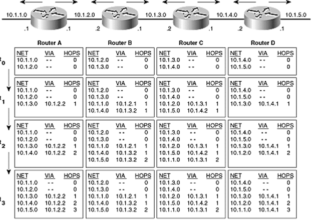
Figure 4.3 from sample chapter of Cisco Press book; also on resources.
Some
examples of routing protocols are:
RIP (v1, v2,
Novell IPX) - Routing Information Protocol. Oldest, distance vector, uses hop
count metric, limit TTLs to 16. Broadcasts entire routing table every 30 seconds
plus updates when stuff changes. Slow convergence. Bad security (will accept
update from anyone). Version 2 fixes some of RIP’s problems.
OSPF - Open
Shortest Path First. Link state, uses complex metric, sends updates only.
Fast convergence. OSPF requires more CPU cycles and RAM in a router than RIP.
IS-IS - OSI
standard
EIGRP -
Enhanced Interior Gateway Routing Protocol. Cisco proprietary protocol (unlike
RIP and OSPF). Uses a hybrid distance vector/link state approach with a
complex metric. Fast convergence but limited to Cisco routers.
BGP
- Border Gateway Protocol
Used on the Internet to
connect autonomous systems. BGP is special in that it must be
robust, scale to 100s of thousands of routes, and use the different networks
fairly and efficiently. (In the early days of the Internet, a router was
called a gateway.) While rarely used on a *nix server, an understanding of BGP
helps understand how the Internet works and should be useful to know.
[Adopted from post
by Iljitsch van Beijnum on 11/24/2010 on Ars Technica:]
Every autonomous system
(AS) is a separate network, connected to other ASes at various Internet exchange
points (IX). To send packets from a host in AS to some destination in another
AS, the packets must cross from one AS to the next at their borders. It is
these border routers (ASBRs) that must select the next AS from among
those it connects with at that IX.
BGP routing is based on
autonomous systems (ASes) exchanging prefixes (ranges of IP addresses)
using the Border Gateway Protocol (BGP). Autonomous systems are generally
ISPs. However, some end-user organizations are their own AS, usually in order
to connect to two or more ISPs at the same time. The IP addresses ISPs give
out to their customers are aggregated into a relatively small number of
prefixes that cover large address blocks, and these prefixes are “announced” (“advertised”)
over BGP to all neighboring ASes. Prefixes make their way from AS to AS, each
adding its AS number to the route, so eventually the entire Internet knows
where to send packets with a given destination address.
From the BGP routing
perspective, the Internet looks like this:
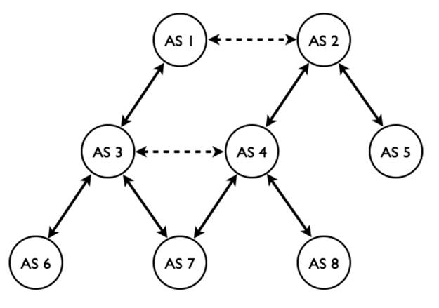
The dotted lines from side
to side are “peering” (also called “settlement-free peering”) relationships
where traffic is exchanged without money changing hands. The solid lines
represent customer-provider relationships, where the customer (the lower AS in
the diagram) pays for any packets traversing the provider’s network (the higher
AS in the diagram).
To populate the routing
tables, route (or prefix) advertisements are made between neighbors. For
example, suppose AS 7 owns (or originates) some IP block, say 192.0.2.0/24.
It advertises “192.0.2.0/24: 7” to AS 3 and 4. They in turn may advertise the
route to their neighbors: AS 3 will advertise “192.0.2.0/24: 3,7” to AS 1, 4,
and 6. AS 4 will advertise “192.0.2.0/24: 7,4” to AS 3, 2, and 8. AS 1 may
also advertise the route “192.0.2.0/24: 7,3,1” to AS 2, which now has two ways
to send packets to that IP block.
To route traffic, the ASBR
compares the destination IP address with its routing table, and selects the
longest matching prefix. For example, 8.8.8.8 might match the prefixes of
8.0.0.0/8, 8.8.0.0/16, 8.8.0.0/18, and 8.8.8.0/24. The last one is the longest
match, and its route will be chosen.
Most of the time, there
will be more than one matching route. In this case, policy determines which is
selected. The economic models are such that traffic flows up the hierarchy,
then sideways, and finally down. Paths that go sideways, then up or down, and
then sideways again only happen if someone is giving away free service, and is thus
rare. With both “192.0.2.0/24: 7,4” and “192.0.2.0/24: 7,3,1”, AS 2 will send
the packets via AS4, who will pay them, and not AS 1, who won’t. Note, the
length, load, and reliability of the route are not factors in the routing
decision.
Another example: packets
from AS 6 to AS 5 may follow the path 6 - 3 - 1 - 2 - 5, where AS 6 pays AS 3,
which in turn pays AS 1, with AS 5 paying AS 2. So all the ISPs get paid, even
though AS 1 doesn't pay AS 2 (or the other way around). However, the path 6 -
3 - 4 - 2 - 5 is not a valid way to get from AS 6 to AS 5. In this case, AS 4
would have to pay AS 2 for this traffic, but AS 3 doesn’t pay AS 4 anything so,
so AS 4 would be giving away service for free. On the other hand, from AS 6 to
AS 8 over the path 6 - 3 - 4 - 8 is fine, because AS 8 is AS 4’s customer so AS
8 pays AS 4 for the incoming traffic.
In its default state, BGP
will trust every route advertisement that it hears from its neighbors, add it’s
AS number to the route, send it to all its other neighbors, and happily give
away service for free. To avoid this, BGP routers must be configured with filters
that make sure only correct, permitted route advertisements are entered into
their routing tables. Also, the prefix advertisements are only sent in
accordance with business relationships (and censorship regulations, since an AS
can’t send traffic to another AS that it doesn’t know about). So even if your
organization was assigned its own AS number, your upstream ISP(s) may filter
out your prefix advertisement and thus nobody will know how to send traffic to
you (it will go the AS who’s IP block includes yours). Finding ISPs willing to
advertise a route to your AS, when your IP addresses belong to a different ISP
(and AS) is difficult, which is why multi-homing to different ISPs is rare.
In 2001, the BGP routing
table included about 100,000 prefixes. But the table grows continuously: in
2006, 195,000 prefixes; in 2007, 240,000 prefixes; and in 2010, 341,000
prefixes. (Show the current BGP stats from cidr-report.org.) The protocol
is aging and showing problems with so many prefixes, and the IRTF (Internet
Research Task Force) is trying developing a successor to BGP. Hopefully this
will address speed, security, IPv6, and allow easier access to
provider-independent address blocks.
Knowledge of the
network graph and the AS-prefix relationships would make it possible to create
filters that could validate the information received over BGP and reject
incorrect or falsified information. There are routing databases where ASes can
register this information. Unfortunately, many organizations fail to do so,
and thus the information that is available is often incomplete. The IETF and
the Regional Internet Registries (RIRs) that give out IP addresses and AS
numbers are now working on a database and certificate infrastructure that would
allow network operators to do exactly this, but it’s not available as of
11/2010.
Network operators simply
don’t know whether CNN’s servers are in Atlanta or Beijing. So when BGP
updates come in claiming the latter, ISPs—well, their routers—have very little
choice other than to install those updates and start sending traffic in the new
direction. 999 times out of 1,000, a rerouting event like this is a routine
change in the network or an equally routine repair of a failure. But that last
one in 1,000 is incorrect—either a mistake or because of an attack of some
kind. The number of such incidents has increased over time and there are a
number of sites that monitor various important IP blocks to make sure they
don’t get re-routed unexpectedly. The saving grace of Internet routing is that
most ISPs carefully filter what their customers send them. So, if I instruct
my BGP router to tell my ISP that I'm the owner of the Windows Update IP
address, my ISP should know better and ignore this BGP advertisement.
When Pakistan
attempted to block YouTube from its citizens (Feb 08), it did so by routing the
YouTube addresses into a black hole—a non-destination destination. It did that
by advertising a /24 prefix for YouTube’s IPs. Due to the longest match rule,
this route would always be chosen over the real /22 prefix. The route was
meant to only be sent to its customer ASes within its borders.
Unfortunately, that
routing advertisement got out to one of their peer ASes, whose advertisement of
the route eventually circled the globe, and left the entire world without
YouTube access. YouTube itself was still there, but no one could see it. This,
perhaps, is the most obvious case of (unintentional) IP hijacking ever, but
smaller attempts are typically just as obvious to the companies or
organizations affected by them. — Ars Technica post by Iljitsch van
Beijnum on 2/25/08.
In April 2010, a set of
BGP advertisements caused 15% of all prefixes to be routed through China,
including those IP addresses assigned to .mil and .gov, for 18 minutes. We can’t
say for sure whether this was a diabolical plan executed to perfection, or a
network engineer doing something really, really stupid (most likely).
In 11/2017, Level
3 communications (recently bought by Centurylink) did the same thing,
knocking Comcast and much of the U.S off the Internet backbone; hosts could
only communicate to other hosts withing their AS.
This sort of problem
is known as a route leak.
Gateways
and Issues
Originally a term used for
a router, a gateway connects dissimilar networks that use different
formatting, protocols, or logical topology. Operates at multiple levels.
Often implemented in software and thus can reside on servers, routers, etc.
Some common gateways:
·
Email
·
mainframe
·
Internet
·
LAN (Ethernet to Token ring or FDDI, includes access servers
(dial-up), often a port on a router is a gateway.)
Use route
or ip route (can handle IPv6 and traffic control via tc) to set static routes including a
default gateway, or to look at the routing table (route -n, ip route,
or netstat -rn). For dynamic routing run a
routing daemon such as gated,
which exchanges information with other routers using RIP.
IP Alias -
Multiple virtual interfaces, one physical interface (a.k.a.
network layer virtual hosting, vs. application layer (virtual hosting used in httpd)). Each virtual interface can
be configured independently including a different IP address. On Linux virtual
interfaces are numbered eth0:0, eth0:1, ... (for physical NIC eth0).
Create one using ifconfig eth0:1 additional_IP ...
The modern Linux IP
kernel code allows multiple IP addresses per NIC, so you don’t need to create
virtual NICs. (Must use the newer ip
maddr command to work with
these, not ifconfig.) In some
cases it may be simpler to just continue using virtual NICs.
In Linux, you treat virtual interfaces
the same as regular ones. The configuration info for eth0:1 in RH goes in /etc/sysconf/network‑scripts/ifcfg-eth0:1.
For Debian you just add a stanza for eth0:1
in /etc/network/interfaces.
On Solaris use ifconfig
hme0 addif additional_IP/prefix up
To have these created at boot time, simply have a file called /etc/hostname.hme0:1 containing a
single line holding the IP number. Further IPs can be allocated by increasing
the :1 to :2, :3 etc.
On BSD you use ifconfig
fpx0 alias additional_IP/32
Two former ICANN
chairpersons recently (11/2011) voiced concerns about the organization’s plan
to start accepting applications for new generic top-level domains (gTLDs) in
January 2012. Tech investor Esther Dyson and Google chief Internet evangelist
Vint Cerf chaired ICANN’s board from 1998-2000 and 2000-2007, respectively.
Cerf says his
concerns about the new gTLD program include the potential to create confusion
among Internet users and new hassles for trademark owners as well as the
logistical obstacles that are triggered by any new domain registrar that
becomes insolvent.
Meanwhile, Dyson
pointed out that “most of the people active in setting ICANN’s policies are
involved somehow in the domain-name business, and they would be in control of
the new TLDs as well.” Dyson notes that although it is worthwhile for them to
attend ICANN meetings and engage in the decision-making process, for everyone
else domain names are just one part of their Internet experience. She says “that
means that the new TLDs are likely to create money for ICANN’s primary constituents,
but only add costs and confusion for companies and the public at large.”
(Reported in TechDailyDose.NationalJournal.com.)
In addition, there are the two-letter country
code TLDs (ccTLDs) for each country listed in the ISO-3166
standard. An example is .us.
The
Atlantic (02/24/11) Nancy Scola — The Internet was nearly splintered
in the late 1990s when Eugene Kashpureff, unhappy with what he saw as the
emerging Net’s dominance by academics, industry figures, and government
entities, established AlterNIC, an alternative domain name registration service
that allowed anyone in the world to register a Web site on Kashpureff’s top-level
domains (TLDs). He later raised the stakes by diverting traffic intended for
InterNIC, which managed the majority of domain name registrations on major
TLDs. Internet Software Consortium co-founder Paul Vixie says fracturing the
domain name system (DNS) would divide the Internet so that users might never
know where to go to locate domains, or what they might get, which could result
in chaos.
Recently [2010], the
U.S. Department of Homeland Security’s Immigrations and Customs Enforcement
division and the Department of Justice seized Web sites thought to engage in
offensive activities, and Congress is considering legislation that would enable
the Attorney General to blacklist Web site names. Such developments have
heightened the controversy surrounding the central role of ICANN and U.S.
influence over Internet governance, and there have been sizable initiatives to
shift power from ICANN toward a globally accountable entity. These and other
sources of tension have raised concerns that a balkanization
of the Internet could result.
(Mozilla operates, as a public service,
a list of all known DNS suffixes under which someone might register a domain
name, at publicsuffix.org.)
The DNS database can be searched with
the nslookup command: nslookup www.redhat.com, or modern
commands:
dig [any] wpollock.com and host
[-a] wpollock.com. Use getent hosts wpollock.com to test your resolver
(dig and nslookup bypass nsswitch
and the resolver, and use DNS directly).
Domain name
front-running (a.k.a. domain tasting) is a technique used
by Network Solutions and other registrars to hold domain names hostage (so you
can only register them via that registrar). A registrar registers a
previously-unregistered domain to itself immediately after someone searched for
it, then holding the domain for several days before it could be purchased by
someone else or at another registrar. ICANN has made this practice illegal
(actually, just impractical; ICANN doesn’t make laws) by imposing $6.75 penalty
per withdrawn name. The number of withdrawn names was 17,665,750 in 6/2008.
Since the fees went into effect, only 58,218 as of 7/2009.
WHOIS
To see who owns what domains and who to
contact to register names within those domains, you must search the whois
database. Start at whois.iana.org,
to see which registrar has the record for a given domain name. (The referrer
line.) Try wpollock.com or hccfl.edu. You can then go to that
registrar’s whois page to lookup the record.
In addition to these websites, there
are a number of tools that find the records for you automatically: www.internic.net and www.uwhois.com,
and the command line tools whois
or jwhois. (Note, these don’t
always work!)
WHOIS data can be
used by bad guys. For this reason, no whois data for .gov or .mil is
available. Additionally, many registrars will allow you to pay extra for an
“unlisted” entry. Those who don’t pay, may just use aliases or completely fake
data; most registrars don’t check that carefully. Consider listing only email
aliases and some toll-free number, so attackers can’t determine personal names
or the organization’s location.
You can also run whois on a network IP address. (Demo
“whois 180.76.0.0”, which had over a dozen IP addresses within
that network attack wpollock.com
in 2/2013).
Examples
of Common DNS Record Types and Lookups
Beside containing name (A) records, the
DNS database contains alias (CNAME) records, number-to-name (PTR) records (for reverse
DNS lookups), domain contact information (SOA) records, nameserver (NS)
records, and mail exchange (MX) records (used to direct email to a specific
host: user@wpollock.com --> user@mail.wpollock.com). TXT records can be
used to add descriptive info for each host. See www.iana.org
DNS Parameters for a complete list.
Every zone must start
with an SOA record, and one or more NS records.
In addition to the standard domain
names, the special domain in-addr.arpa
is used to support reverse DNS lookups, where you have the IP address
and want the name. (MTAs use this to detect spam mail: If the host claims to
be mail.foo.com but the reverse DNS lookup on their IP address is fake.bar.com
then the email is dropped.) For example, if the host www.foo.com has the IP address of 200.32.40.6, then the normal record is
www.foo.com. IN A 200.32.40.6
and the reverse record is
6.40.32.200.in-addr.arpa IN
PTR www.foo.com.
Not all networks have
DNS servers, so another file is used to map network IP numbers into names, /etc/networks. On Solaris, that
host’s FQDN is in the file /etc/defaultdomain.
Note that a given IP address can have
several names, known as aliases. (See CNAME records, below.)
DNS is also used to support domain
style email: user@domain
must map the domain name to a particular IP address of your company’s mail
server, via an MX record. These have a priority number (lower is preferred).
MX is so useful, the
concept has been extended to other services using SRV or WKS records. A URI
protocol of DNSSD: says to use DNS service discovery (to locate parameters such
as a port number). See RFC-6763.
A host running some client programs
(web browser) usually won’t be running a local DNS server. Such programs need
to know the IP address of a name server and whether to use the hosts file, DNS,
NIS+, LDAP, or a combination to resolve names to IP addresses. These programs
all use a standard API known as the resolver or the resolver
library. Various files in /etc
are used to configure the resolver: host.conf,
resolv.conf, nsswitch.conf, hosts, and possibly others.
(Solaris: nsswitch.*)
DNS has proven very effective and
efficient in the world. Microsoft has a competing scheme called WINS that does
the same task as DNS but for LANS only. Also, some servers now have dynamic IP
addresses assigned, which requires that the DNS records be updated frequently.
A system called dDNS (dynamic DNS) is available for this. It is
possible to use multiple services; a common setup is to use both the hosts file
and DNS.
The most popular DNS server software by
far is called BIND. You can use BIND to set up a primary, secondary, or
caching-only nameserver (called named).
The /etc/named.conf file
configures named for its type, where to find its zone records for all domains for
which it is authoritative, and other information. To run a DNS server, you
create the records in the proper format and put in the proper files, edit the named.conf file, update the firewall
rules, and finally arrange for named to run at boot time.
If you set up an authoritative DNS
server, you can verify its records using these services: www.dnsstuff.com.
(Show.)
DNS
Caching
Normally *nix systems don’t cache DNS
information (looked-up IP addresses). Most applications will only lookup a
name once though. To improve performance (at the cost of memory), you can have
the system remember previous lookup results. You do this by enabling the name
server caching daemon, nscd.
One consequence of caching (application
or system) is that if the information changes, the old information will still
be used. To flush the cache, simply restart nscd and/or the application(s).
Long ago, I used HCC
as my ISP. Their DNS was unreliable, so I put the IP addresses of YborStudent
and other HCC servers in my hosts file. Eventually the information changed but
by then I had forgotten all about the entries I had made to hosts. For several
weeks after that, I had no email service from home! (Eventually I remembered
to check that file.)
DNS
Round-Robin
A simple form of load-balancing
requests among a group of servers is to have a DNS server return a different IP
address each time some name is looked-up. (Try this: host scs.msg.yahoo.com,
used for Yahoo Messenger service.) This is done automatically by BIND and some
other DNS servers if there are multiple “A”
records for the same name. (This is discussed further, below.)
This system works but not well. The
problem is caching. If some organization uses a caching name server then until
that entry expires all lookups from within that organization will use the same
IP.
I use Pidgin IM
client to work with Yahoo Messenger. However, some of the servers used by
Yahoo in their round-robin for scs.msg.yahoo.com
are broken (at least with Pidgin). Unless you flush the cache (say by
rebooting) Pidgin keeps trying the same IP! You must flush the cache (restart nscd) repeatedly until you get a
working IP. (With Windows, you can use the command ipconfig/flushdns.) You can also add an entry to /etc/hosts, but if Yahoo changes their
servers or IPs you will need to remember to change that!
Nameserver
Lookups
(Show DNS-lookup GIF web
resource.) The typical lookup of a host’s IP address given a name by
the DNS is to see if it is a FQDN or just a partial name. If not
a FQDN, the NS constructs one from the default or search domain listed in the
config file (Qu: which file?). Next it checks to see if it has cached this
name previously. If so we are done.
If the FQDN is not in the cache, DNS
checks the domain name to see if it is authoritative for this domain. If so it
looks up the name in its DB files. If not, it must ask some DNS on the Internet
to look it up. If it has previously cached the IP address of a NS
authoritative for any part of the domain, it can ask that NS to resolve the
name for us. If not, the NS consults a hints file that gives the IP
addresses of a dozen or so DNS that know the IP addresses of the NSs that are
authoritative for the TLDs. (Say that three times fast.) (Show hints file root.cache.)
You can get the
newest version and use it with:
$ wget --user=ftp --password=ftp \
ftp://ftp.rs.internic.net/domain/db.cache
# cd /var/named/chroot/var/named
# mv root.cache root.cache.OLD
# mv ~/db.cache root.cache
# chgrp named root.cache
# rndc reload
(Demo resolving www.hccfl.edu: Not in cache,
already a FQDN, so our NS finds the IP address of the NS for “.”, then edu, then asks that NS the IP of the NS for hccfl.edu, than asks that NS for the
IP of host www.hccfl.edu.)
If the lookup fails and additional
search domains were listed, the next FQDN is tried.
Summary: Resolver-only: hosts, networks
(optional), resolv.conf, nsswitch.conf, host.conf.
Split DNS
Most large organizations already
separate their internal network from the global Internet. Only have public
servers (web, mail, etc.) available to all external clients are listed in the
Internet-facing DNS server. It makes sense to prevent information leakage into
the internal network as well. There should be two separate name spaces: One
that could only be accessible from internal hosts (which lists the internally
accessible hosts and internal IPs), and one accessible from the outside listing
only public servers and their public IPs). This strategy is often called Split
DNS. There are several ways to achieve this, including separate DNS
servers and special configuration for (newer versions of the) BIND DNS server.
(Show CWS’s named.conf.)
DNS Security
The United States government has
announced that all .gov domains will begin to transition to the secure DNS
protocol known as DNSSEC, and must complete the adoption process by
December 2009. .gov is the
second gTLD to announce such a switch; .org
announced its conversion to DNSSEC in July of 2010.
The primary purpose, and main security
feature, of the DNSSEC protocol is its ability to protect users from DNS
cache poisoning. Poisoned DNS servers have been fooled into returning
false information in response to a DNS lookup request. DNSSEC solves this
problem by requiring that all DNS records be digitally signed. This allows the
DNS server to check and confirm that the information it’s about to return to
the client actually points at the address it’s supposed to point at.
DNSSEC is not well liked by everyone.
It complicates setup and maintenance of DNS servers, doesn’t encrypt the data,
and there is the problem of who will hold the private keys for the root
servers.
The Internet Corporation for Assigned
Names and Numbers (ICANN) announced it will generate a new top-level, Root Zone
Key Signing Key (KSK) in Fall 2017. This will be the first time the key has
been changed since its inception in 2010. Admins will need to update their
systems.
DNSSEC
Overview and setup
ZZZ
The first-ever criminal
arrest for domain name theft has been made, Daniel Goncalves in New Jersey
7/30/2009. In 2005 husband and wife Albert and Lesli Angel with partner Marc
Ostrofsky (known for his sale of the domain business.com
for $7.5 million) bought P2P.com
for $160,000. In 2006 Goncalves allegedly hacked into the Angels’ e-mail
account, obtained login details for the couple’s GoDaddy.com
account, and transferred the domain to an account he controlled using a fake
name. He even falsified PayPal transaction records to make it appear as though
he had rightfully purchased P2P.com
for $900. Gonclaves then put the domain up for sale on eBay, and sold it to LA
Clippers NBA player and part-time domain name investor Mark Madsen for
$110,000.
(The Angels contend
that subpoenaed Godaddy.com
records reveal that the registrar knew that Goncalves was implicated in two
other domain thefts at least one month prior to the P2P.com theft.)
Nameserver Configuration
The file /etc/named.conf is used to configure the BIND
nameserver. (Older versions of BIND used the file /etc/named.boot.) This file tells named to be a primary (or master),
secondary (or slave), or caching-only nameserver.
Note! If using chroot, then be sure to copy named.conf into the jail after all
changes!
If caching-only this file says to which
nameserver to forward the DNS requests.
For a primary nameserver the names and
locations of the DNS DB (the zone records) files must be given.
For a secondary the IP address of the primary
nameserver must also be supplied.
Note that a given nameserver may be
primary for some zones and secondary for others. (All nameservers will cache
in RAM the results of any previous lookup. Every nameserver should be a
primary NS for localhost (if DNS
only and no files are used), and the 0.0.127.in-addr.arpa
domain (in any case).
The syntax for this file is similar to
C programs: white-space is not significant (put blanks and tabs and newlines
almost anywhere), “//” and “/* ... */”
comments are allowed, and the directives go in sections delimited
by curly braces (“{}”). Each
directive ends with a semicolon.
(Show named.conf samples. Explain setup
for each type of nameserver.)
options { directory "/var/named"; };
controls { }; //Disables rndc
zone "." { type hint; file
"root.cache"; };
zone "hcc.com" { type master; file
"db.hcc.com"; };
zone "35.168.192.in-addr.arpa" {
type master; file
"db.192.168.35"; };
zone "0.0.127.in-addr.arpa" {
type master; file "db.127.0.0"; };
There are a zillion options you can
change in this file, but a basic file includes some options and a list of zones
to serve. Additionally this file controls logging and security for your DNS
server: who is allowed to make updates, who is allowed to make queries, who can
do zone transfers, etc. (Logging directives are described below.)
In the modern world DNS security is a
major issue and you must secure your server. BIND implements two schemes for
this, TSIG and DNSSEC. TSIG allows a shared secret between servers to
be used to authenticate one to the other, to allow dynamic updates or zone
transfers. This is similar to the PPP PAP security. DNSSEC is a more through
security system that digitally signs the resource records. This is similar to
SSL and PKI security used by websites and browsers. With DNSSEC, the data can
be verified as legitimate. However, this is more difficult to set up and as of
2008 isn’t widely used.
Some simple security measures you can
take include restricting queries to your recursive (caching) servers,
restricting zone transfers, and forbidding recursive queries from authoritative
servers. You should periodically run a DNS vulnerability scanner, and audit
your firewall and router configurations. You can take many other security
measures, such as setting the version data to a fake value, or (more
importantly) configure DNSSEC.
DNS Database: Zone Files
Files contain resource
records (RRs) for zones. Common types are: SOA, A,
AAAA, PTR, CNAME, NS,
MX, TXT, and some others. See RFC-1034
which describes DNS concepts, and RFC-1035,
which describes the zone record file format. (Show example zone DB files.)
The zone files are ASCII
text. Then contain blank lines, directives, and RRs. They can contain
comments, from a semi-colon to the end of the line. A number of characters
have special meaning in the file, so you must escape those with a
backslash (‘\.’, ‘\@’, ‘\;’,
and ‘\\’ are the most common).
Also, non-ASCII bytes can be specified using \nnn,
where ‘nnn’ is exactly
three decimal digits.
The file usually starts
with some comments, and then some directives that apply to the rest of the
file. After that, an SOA record must be present (before any other RRs in the
zone.)
RRs must be all on one
line. If desired, the data portion of any RR can be enclosed in parenthesis,
which allows the RR to span multiple lines. (This is commonly done for SOA,
and rarely for any other RRs.)
The RRs all have a similar
format:
<domain
name> [<TTL>] [<class>] <type> <RDATA>
<domain
name> [<class>] [<TTL>] <type> <RDATA>
Omitted <TTL> and <class> values default to the last
explicitly stated values.
Remember, the <RDATA> may be enclosed in
parenthesis if you wish to break up a long list over several lines.
Directives
There are two directives
commonly used at the top of your zone files:
$TTL 86400
$ORIGIN example.com.
$TTL 86400
sets the default TTL (after this interval, they should ask us again.) A day to
a week (or even longer) is fine, and you can override this value on individual
records. (86400 = 1 day.) This directive was standardized in RFC-2308.
To make a major
change to the DB, set this to a short interval, wait for the old value, make
the change, and then reset the value.
$ORIGIN resets the current origin for relative
domain names (those that don’t end in a period.) While the default domain
for a zone is usually determined by named from the zone name in the named.conf file, it is common to put
it again here. When you type in a relative domain name in some RR, the origin
is appended. With the origin as shown in the example above, the name “www” in the file refers to the domain
name “www.example.com.”. (The
common error is to use “www.example.com”
in the file, which actually refers to “www.example.com.example.com.”.
Always double-check those dots!)
Within the rest of the
file, the origin can be referred to with “@”.
In addition, RRs that are indented are assumed to start with the same name as
the previous record; so if your zone file starts off like this:
$ORIGIN
example.com.
@ SOA ...
Then these three RRs are
equivalent:
example.com.
MX 10 192.0.2.1
@ MX 10 192.0.2.1 ; the origin
MX 10 192.0.2.1 ; the previous RR
The SOA
record
Each zone should have one
SOA (start of authority) record at the beginning, describing
default values used by the DNS server. A typical SOA RR might look similar to
this:
example.com. IN SOA ns.example.com.
hostmaster.example.com. (
2011080800 ; serial number
172800 ; refresh = 2d
900 ; update retry = 15m
1209600 ; expiry = 2w
3600 ; minimum = 1h
)
Where:
example.com. is the root name or origin of
the zone (typically the “@”
short-cut is used, which is the name is set with the $ORGIN directive);
TTL or time to live (not shown in
this SOA example) is the amount of time a client can cache this record for
before checking an authoritative server for a fresh value. (This was optional on
all record types, was seldom used, and is now deprecated as a default TTL can
be set);
IN is the class, almost always IN for Internet and may be omitted (some
historical values are allowed);
SOA is the record type (start of authority);
ns.example.com. is the name of an authoritative name
server for this zone (an NS
record is used to translate this name to an IP address, usually the master);
Email address hostmaster (add to MTA’s aliases file), with a dot instead of
an “@”. The “@” for SOA expands to the zone this
file is for (from the named.conf
file). Ex: j.smith@example.com ‑‑> j\.smith.example.com (note
the backslash in front of the literal dot).
The serial number must
be updated every time any change at all is made to this file. If you
fail to do this, the secondary NSs won’t do any zone transfers. Use an
integer that will fit into a 32-bit unsigned integer format (max value is 4,294,967,295,
and the max allowed increment to the previous value is 2,147,483,647). Don’t
use a decimal point, it won’t work the way you might think! The recommended
format is YYYYMMDDnn.
If you make a mistake
and increment the serial number too high, and you want to reset the serial
number to a lower value you need to change it in two steps: (1) Take the
current serial number and add 2,147,483,647, the maximum increment allowed. If
this value is greater than 4,294,967,295, then set it to that instead. Next
perform a zone transfer and wait one refresh interval (to make sure). (2) Now you
can set the number to the desired/correct one and restart or reload the zone
again. This works because when the number exceeds the maximum it “wraps
around” (overflows actually) so “1” appears “higher”. (See RFC-1982
for details.)
The refresh is the
interval in seconds that sNSs should check the pNS for updated records.
Typical values are 1200 (20 minutes) for volatile data, to 43200 (2 hours) for
larger networks, and occasionally as long as a day for small sites that rarely
change. Note that until the sNSs are synced, some DNS lookups will return the
old information! Newer versions of DNS servers (including BIND) will send a
message to sNSs whenever a change occurs, so setting refresh to a day or longer
is reasonable. (Recommended range: 20 min ... 12 hours)
Retry is the interval that a sNS
should wait before contacting a pNS again if the 1st attempt failed. Typical values
are in the range 2 minutes to 2 hours.
Expire is the point a sNS stops
resolving names using its (out of date) zone records (in the event the pNS
can’t be contacted for a long time). Normal range is between one and two weeks,
but could be as long as two months (it depends on who you ask).
Minimum is historically (BIND 8
and earlier) the minimum (and default) ttl value for records,
which is the amount of time other (non-authoritative) NSs or resolvers should
be allowed to cache the record. In fact this field has been overloaded in the
past to have three different meanings: the minimum TTL value of all RRs in a
zone (this use was never popular), the default TTL of RRs which did not contain
a TTL value, and the TTL of negative responses (that is, how long should a
client cache a no matching records found (NXDOMAIN)
response). Today this field only has that last meaning (called the negative
cache TTL). You use the $TTL
directive to set the default TTL. Recommended value is in the range 1 hour to
1 day. See RFC-2308 for
details.
The standard states
that TTL values must be expressed as a number of seconds. However, BIND (and
possibly other servers) allow an easier syntax of <num><letter>,
where <letter> is s, m, h, d, or w for seconds, minutes, hours, days, or
weeks.
NS records
NS records link a domain name to the
nameserver that manages its zone records. (I.e., the “parent” zone has NS
records for each “child” zone, as well as for its own zone.) The data should
be a domain name (not an IP address) of any authoritative server. Every domain
should have at least two nameservers, preferably located far apart (so one is
always available even if a disaster occurs). These are all authoritative,
however one of these is designated as the primary NS and the others are
secondary (or master/slaves).
In 9/2012, GoDaddy
had a router misconfiguration that causes thousands of hosted websites to be
unavailable for five hours. Had GoDaddy used two NS records pointing to
different networks, that wouldn’t have happened. Instead, both NS records
pointed to the same network. (Note, wpollock.com does that too; but the
nameserver is the same host as the web server, so if one is not available,
neither is the other.)
Queries to a nameserver listed in an NS
record for your domain should always result in an “authoritative” response. If
not, this is called a “lame delegation”. This can happen if the
secondary has bad data, or if some other NS thinks it is authoritative for your
domain. (Imagine if I set up BIND in YborStudent.) You will also see these
when someone adds NS records pointing to your NS without permission, or when
the parent NS doesn’t have the same NS records as you do.
BIND will log lame delegations when it
detects them. Often you have no control over those other nameservers (and they
may not even be for your domain). To prevent these log messages from filing
your log files you can add this option to named.conf
(add lame server fix project, see page 461 in Hunt book):
logging
{
category lame-servers { null; };
};
There are special
considerations if the name server’s name is in the zone it servers, e.g. ns.example.com for the zone example.com. See glue records,
below.
A, AAAA, CNAME,
and PTR Records
A
records are the most important, used to translate a name to an IP address. It
is legal to have several different A
records with the same IP address, which is preferred in many cases to having CNAME records. IPv6 uses AAAA records:
host1.example.com
IN AAAA 2001:db8::1
CNAME records are alias names.
Their main purpose is to provide common functional names to hosts, such as
ns1.example.com, www.example.com, ftp, mail, etc. The servers should have real
names unrelated to their functions. This scheme makes it easy to migrate a
service to a different host, by just changing the CNAME to refer to a different
host.
PTR
records are used for the reverse mapping of addresses to names. They go
into a different zone file used for this purpose. A common error is to update A records and forget to update the
matching PTR records!
The PTR
record does works in a strange way: it does a normal (“forward”) lookup on a
domain name composed of the reversed IP address, in the in-addr.arpa domain. Thus, the PTR record that matchis this A record:
www.example.com.
A 192.0.2.2
would look like this:
2.2.0.192.in-addr.arpa
PTR www.example.com.
The IPv6 record works like the IPv4
version but uses the ip6.arpa
domain, and it cannot use the shortcut notation (note this is all one long
line). For the AAAA record
example above, the PTR record
is:
1.0.0.0.0.0.0.0.0.0.0.0.0.0.0.0.0.0.0.0.0.0.0.0.8.b.d.0.1.0.0.2.ip6.arpa.
PTR host1.example.com.
It is legal in BIND to have multiple
A or AAAA records for the same name and
with different IP addresses. Along with short TTLs, this provides a simple
load distribution mechanism (not a true load balancing one) as BIND will answer
queries for this name with each address, in a round-robin fashion.
In practice, clients
who do a lookup for A and AAAA records will get all A and AAAA
records, not just one. The server should rotate the order these are returned,
since most clients will just use the first (or last) one.
MX Records
MX RRs are used for email to say where
email should be sent. It is a good idea to add an MX record for every host (or
use a wildcard record; see below), so if someone sends mail to a user on that
host the mail will be sent to the real mail server, e.g., root@foo.example.com or root@localhost, if that host isn’t
running a mail server then the mail will sit in a queue someplace until it
bounces back to the sender.
MX records contain a priority
value so you can list a backup mail server. If two or more are listed with the
same priority then BIND will return them in a round-robin fashion (useful to
distribute the load if the TTL is small for these records).
DKIM or domain
keys identified mail is another email-related RR type.
Wildcard
Records
Many RRs use IP address and FQDNs as
data types. BIND permits several short-cuts to reduce the amount of typing you
need to do. One such short-cut is confusing, the wildcard name.
Consider this:
*.example.com.
MX 10 192.0.2.10
This applies to any host in the example.com domain not listed
in the zone records. In other words, it doesn’t apply to the whole domain, it
is more of a default record so you don’t have to add (in this example) MX
records for every host.
Glue Records
When adding a NS record, you need to
list the FQDN of the nameserver, not its IP address. This is a problem if you
are hosting your own nameserver. Suppose you own the domain hcc-online.com, and have an NS record
stating that the authoritative DNS server is at ns1.hcc-online.com.
Can you see the problem? When someone looks up the name cws.hcc-online.com, the authoritative
GTLD server (for .com) will find
this NS record. To get the IP address of that, it will try a recursive lookup
of ns1.hcc-online.com, which
finds the NS record, which triggers a lookup, which finds the NS record, which
triggers a lookup, ...
To solve this issue, the .com server also needs the A record
for ns1.hcc-online.com, even
though it isn’t authoritative for that domain. Such address records are called
glue records. Note, you don’t need these if your nameserver is hosted
within some other domain. For example, if the hcc-online.com
NS record pointed to ns5.hccfl.edu,
a lookup would find the IP of that nameserver. You only need the glue records
when hosting a nameserver with a DNS name within that domain itself.
Other Record Types
HINFO records can be used to
list host information: hardware and software versions. This allows your DNS
server to maintain an inventory for your organization. However today it is
considered a security issue to tell people that information. If you chose to use
these records you should be sure to set up your BIND security so the world
can’t see these records!
RP (responsible person) is a
record that lists information about the person responsible for that host. It
lists an email address and the name of a TXT record for more information (e.g.,
phone number).
TXT records have no fixed
purpose. A number of uses are common: for RP record information, for SPF email
anti-spam records (old style), etc.
SPF records for email anti-spam
(new style). These are exactly the same value as the TXT records, and are
generally considered deprecated. However, BIND 9 complains if you have the one
without the other, so I usually add it anyway. See the Wikipedia SPF
record article for more info.
SRV records allow administrators
to use several servers for a single domain, to move services from host to host
with little fuss, and to designate some hosts as primary servers for a service
and others as backups. These RRs work similarly to MX RRs for email, but can
be used for any services (e.g., to designate a backup web server). SRV RRs are
defined in RFC-2782, but here’s an example stolen from www.pantz.org,
for a load-balancing web service with backup:
#_Service._Proto.Name
Class SRV Pri Weight Port Target
_http._tcp.www.pantz.org. IN SRV 0 2 80 www.pantz.org.
IN SRV 0 1 80 www2.pantz.org.
IN SRV 1 1 81 www3.pantz.org.
In the record above, requests for the
website www.pantz.org:80 will go
to www.pantz.org:80 and www2.pantz.org:80. www.pantz.org will get twice as many
queries as www2.pantz.org (due
to the weights assigned). If both those hosts go down, the queries will go to www3.pantz.org:81 instead (due to the
priority assigned). (Note the underscores in front of the service and protocol
names.)
BIND Zone File Format
Certain zones should always be present
in nameserver configurations:
primary localhost localhost
primary 0.0.127.in-addr.arpa
127.0.0.1
primary 255.in-addr.arpa
255.255.255.255
primary 0.in-addr.arpa
0.0.0.0
These are set up either to provide name
service for “special” addresses, or to help eliminate accidental queries for
broadcast or local address to be sent off to the root nameservers. (Also,
depending on your nsswitch.conf
setup, a failure to resolve localhost and/or
localhost.localdomain may just
fail, rather than consult /etc/hosts.)
All of these files will contain NS and
SOA records just like the other zone files you maintain, the exception being
that you can probably make the SOA timers very long, since this data will never
change. Modern BIND includes all these by default (via an include statement in
named.conf for /etc/named.rfc1912.zones.)
Sometimes your ISP
(or whoever your DNS provider is) hijacks non-resolvable domains, usually to
capture web traffic. You get directed to a page of ads or worse, rather than
an error message. If this happens to you, check by doing a reverse DNS lookup
on your DNS IP address, for example:
$ host
208.67.219.132
132.219.67.208.in-addr.arpa domain name pointer hit-nxdomain.opendns.com.
“OpenDNS.com” has a reputation for
this. VeriSign had a PR disaster some time ago for doing this.
The solution is
simple: Run your own local caching nameserver (and configure the resolver to
use it). This should improve performance too.
Lecture 15 ― Remote Access
Remote access allows
remote users to communicate with networked hosts (typically just servers), or
enables communications from the hosts on a network to remote hosts and
networks. Remote access includes the ability to run applications and access shares
(files or printers) remotely. Another use is for remote console access (so you
can boot a host remotely). (Also KVM (in this case, keyboard, video, and
mouse) and serial consoles are used for this.)
Microsoft used the term RAS
(for Remote Access Server), others use NAS (for Network Access Server).
Commonly used remote access client software uses protocols such as PPP, SSH,
telnet, and many others. This type of remote access provides console (text
user interface, a.k.a. command line interface) access only.
But remote access also allows users to
view and use GUI desktop sessions remotely. This type of remote access is
given a separate name and often requires different client and server software.
Microsoft calls this terminal services.
X Window can be considered as the Unix
version of terminal services (via XDMCP). X doesn’t allow sharing of desktops
however. Software such as VNC is used for that.
Terminal services are very useful to
SAs, for providing help desk personnel access to users’ desktops. It can be
used for training purposes too.
Terminal services also allow
applications to be installed on central servers, while users use terminal
service clients to access them. (Also known as client-server computing, using thin
clients. A Web based service, accessed remotely via a web browser, is a
perfect example.)
In addition to the standard Microsoft
terminal service software bundled with all (modern) Windows versions, there are
proprietary products for terminal services that use proprietary protocols.
Some examples are PC Anywhere, LogMeIn, and Citrix WinView and WinFrame. (MS
terminal services server and client are in fact licensed from Citrix.) HCC used
“DSview”, which I used to access the console of YborStudent. (I no longer have
console access.) Macintoshes can use Apple Remote Desktop.
Since even Unix SAs must occasionally
access users’ (Windows) desktops, you will need to know the protocols and port
numbers used for this, use Unix clients that can access Windows desktops, and
set up Unix servers that can provide application access to Windows clients (I
think this is much less common though). MS Terminal services use the remote
desktop protocol (RDP) over port TCP/3389 by default. MS provides an
ActiveX component to provide client access via a web page, a cell phone/PDA,
etc. Unix systems use rdesktop
open source software for this. (There are VNC clients and servers for Windows
as well, but RDP is built into all Windows hosts; the client is mstsc.exe.)
Remote users typically must
identify themselves to a network before access is granted; this is known as logon
or logging in. Besides authentication, remote access (today) should use
encryption. Systems to allow remote users secure access to a network are known
as virtual private networks (or VPNs). With a VPN, a remote
user’s host appears multi-homed, with a virtual NIC used to access the central
network.
Two commonly used
authentication servers for allowing remote users to authenticate include Remote
Authentication Dial-In User Service (RADIUS) and Terminal Access
Controller, Access Control System (TACACS+). RADIUS is more widely
deployed today, and can be used to authenticate Wi-Fi clients as well. (The
successor to RADIUS is a protocol called Diameter.)
Cisco equipment generally supports both protocols. RDP traditionally used RC4
encryption, but today can use any FIPS-140 compliant method. (X and VNC can be
tunneled through SSH or SSL.)
SSH [Advanced
uses are discussed in the CTS-2311 Unix/Linux Security course]
SSH is a secure replacement for
telnet. It normally runs on port 22. Your firewall must allow incoming
connections to the SSH port on the server. Basic connection to a remote host
(which must be running an SSH server) is: ssh user@host.
SSH is also a secure replacement for
FTP: scp file user@host:/path.
(Relative pathnames are relative to user’s
home directory on the remote host.) Both scp
and sftp use the same server
(and port number); they are implemented as a sub-system of the SSH server.
(Most other services are not sub-systems of SSH, but rather ordinary server
daemons that will use an SSH or SSL tunnel.) OpenSSH allows the Sys Admin to
change the FTP subsystem to use; allowing you (for example) to use vsftpd for
anonymous FTP, SFTP, and FTPS.
You can run commands on the remote
system and have input and output from your local system, sent over the SSH
connection.
To run a non-GUI command: ssh user@host /pathname/to/command.
(Note, the remote system won’t use PATH
to locate a command, but you can use “/bin/sh
-c "command"” for that.) SSH will forward
stdin and stdout from your system to the remote command’s stdin and stdout.
(So you can pipe something into ssh, and have the remote command read it from
its stdin.)
To run a GUI command (and have
the X windows appear on your local system), run: ssh ‑X user@host /pathname/to/command
(lower case x will disable X forwarding). This can be used to run any GUI
program on the remote host, while having its GUI windows appear on your host.
(If you need to use Windows, install Cygwin and turn on the X server included.)
Finally, SSH can be used to tunnel
other services. This provides a secure communications path for otherwise
insecure protocols (LPD, LDAP, X, etc.). Some examples:
ssh user@host -L 82:securewebserver:80
(point browser at localhost:82
to use this)
Socks proxy: ssh -D 1080 user@host
SSH Host
Keys
Each SSH server has a key so that when
a client connects to a server the identity is confirmed (to prevent man in the
middle attacks). Clients keep a copy of the keys of each host they connect
with, in ~/.ssh/known_hosts.
If the server has not been connected to before, you will see the following:
The authenticity of host 'server (192.94.73.5)'
can't be established.
RSA key fingerprint is 53:2a:b3:92:a6:88:ca:c0:ff:c2:1b:d1:53:11:fc:4e.
Are you sure you want to continue connecting (yes/no)?
If for some reason the server has
changed its key (often after a server update) or someone is spoofing the site
(a man in the middle), you see something like this:
$ ssh user@host
@@@@@@@@@@@@@@@@@@@@@@@@@@@@@@@@@@@@@@@@@@@@@@@@@@@@@@@@@@@
@ WARNING: POSSIBLE DNS SPOOFING DETECTED! @
@@@@@@@@@@@@@@@@@@@@@@@@@@@@@@@@@@@@@@@@@@@@@@@@@@@@@@@@@@@
The RSA host key for server has changed,
and the key for the according IP address 192.0.2.123
is unknown. This could either mean that
DNS SPOOFING is happening or the IP address for the host
and its host key have changed at the same time.
@@@@@@@@@@@@@@@@@@@@@@@@@@@@@@@@@@@@@@@@@@@@@@@@@@@@@@@@@@@
@ WARNING: REMOTE HOST IDENTIFICATION HAS CHANGED! @
@@@@@@@@@@@@@@@@@@@@@@@@@@@@@@@@@@@@@@@@@@@@@@@@@@@@@@@@@@@
IT IS POSSIBLE THAT SOMEONE IS DOING SOMETHING NASTY!
Someone could be eavesdropping on you right now (man-in-the-middle attack)!
It is also possible that the RSA host key has just been changed.
The fingerprint for the RSA key sent by the remote host is
8a:52:a2:3f:72:7a:35:7e:06:aa:9b:f2:32:45:64:d5.
Please contact your system administrator.
Add correct host key in /home/user/.ssh/known_hosts to get rid of this message.
Offending key in /home/user/.ssh/known_hosts:13
RSA host key for host.example.com has changed and you have requested strict
checking.
Host key verification failed.
To fix this, edit the appropriate known_hosts file, and update (or
delete) the offending host key. Notice the message tells you the line number
you need to edit/delete; in that file, each key is a single (long) line.
One proposed use for DNSSEC
is to securely hold SSH host keys. Users never check those hex fingerprints
anyway. This would eliminate the need for a known_hosts file.
SSH – Key
login
SSH can use keys as a replacement for
passwords to login. SSH uses a public key system. You generate
a pair of keys, and copy the public one to any remote hosts you wish. The
private key stays on the local system. This enables “one-click” login to
remote sites. This non-interactive login is useful for scripts.
Each public key (at least in OpenSSH,
the most popular suite for *nix) is one base-64 encoded line, in the file ~/.ssh/authorized_keys on the remote
system. (The private key stays on one host, or you can put it on a flash drive
and carry it around with you.)
To generate a new ssh key pair,
run ssh-keygen. I
recommend using the option “-C user@host”. This adds a comment
to the end of the public key, useful for identifying which key is which in the authorized_keys file.
By default, an RSA key pair is
generated, with the private key (the “identity”) in the file “~/.ssh/id_rsa”, and the matching
public key in “id_rsa.pub”. If
you use the “-t dsa” option, DSA keys are generated
instead; some folk think those are more secure. (They were more secure before
various RSA bugs were fixed.) The private key can be encrypted with a
password/passphrase that you will need to enter each time you wish to use that
key.
Most SSH systems use
proprietary formats for key files. There are standard formats however: RFC-4716
(SSHv2) format, PKCS#8, and PEM. If you use a tool such as PuTTY to generate
the key pair, you will need to use that tool to convert/export/save the public
key in one of these formats. Then you can convert that to OpenSSH’s format
using ssh-keygen -i file.
You don’t have to password protect your
private key. However, it is a security issue to have an unencrypted private
key file. A password protection for this file is recommended, but that
removes the much of the convenience of keys. Keys can be cached in RAM using
programs known as key agents. You only need to enter the
password once per login (or even once per boot). However, encrypted private
keys, even with key agents, would prevent a server from having an unattended
reboot (as some human would need to enter the key password). Many
administrators opt for convenience and use an unencrypted private key file.
(Note attackers can recover data from RAM on a laptop, within a few minutes
after powering it off. This is yet another example of the trade-off between
security and convenience.)
The last step is to have the public key
appended to the authorized_keys file of any remote systems you want to use
(from that identity). OpenSSH includes a simple utility you can use for that: ssh-copy-id -i path-to-private-key.
Note that it is the public key that gets copied, but the command wants the path
to the matching private one.
SSH supports many powerful uses and
features not covered here.
VPNs —
Virtual Private Network (also discussed briefly in the security
class)
A VPN uses tunneling to connect several
small LANs into a single LAN. The packets sent at location A are picked up by
the VPN, sent across a tunnel (across the Internet using an encrypted session),
and re-sent at location B. Thus the LANs A and B appear to be a single LAN.
Note how similar a VPN is to using an SSH tunnel (which doesn’t automatically
forward all traffic). Some VPN technologies are IPSec (the original
encrypted one) and SSL/TLS (userspace one, easier to route), and other
proprietary ones.
A TAP
device is a virtual Ethernet adapter, while a TUN device is a
virtual point-to-point IP link. VPNs could use either.
Some common VPN software packages are:
OpenVPN (SSL
based),
OpenSwan (IPSec based),
Kame, ported from BSD (IPSec based), and
Hamachi (noted for its ease of use; now owned by LogMeIn).
SSH can provide
tunnels as well. But all SSH tunnels travel through a TCP-in-TCP tunnel (using
port 22 by default). Tunneling TCP in TCP doesn’t work well when the network
is noisy or congested. OpenVPN can be configured to tunnel all traffic through
any TCP or UDP port. (With either choice, dropped packets can be a bother.)
You can set up an OpenVPN tunnel easily
between two hosts. Suppose the client has IP 192.168.2.2 and the (remote)
server has IP of 192.168.1.1. Then on the (remote) server:
#
openvpn --remote 192.168.2.2 --dev tun0 \
--ifconfig 10.0.0.2 10.0.0.1
And on the client:
#
openvpn --remote 192.168.1.1 --dev tun0 \
--ifconfig 10.0.0.1 10.0.0.2
The tunnel runs over 1194/UDP by
default, so make sure that port goes through all firewalls between the hosts.
(It is common to configure OpenVPN to run over 443/TCP to avoid the firewall
issues, but then you have the TCP-in-TCP issues.)
From the client, the remote server has
IP 10.0.0.2. You can run any protocol to that IP and it goes over the tunnel
(e.g. “ssh user@10.0.0.2”).
This tunnel doesn’t encrypt any traffic
by default. You can generate a shared key and store that in a file at
each end:
#
mkdir /etc/openvpn/keys/
# cd /etc/openvpn/keys/
# openvpn --genkey --secret static.key
# chmod 0400 static.key
(You can also use public key exchange
methods to share a dynamic session key.)
You can save the tunnel config info in
a file, and automate the tunnel setup. On the server:
dev
tun
ifconfig 10.0.0.1 10.0.0.2
secret /etc/openvpn/keys/static.key
And on the client:
dev
tun
ifconfig 10.0.0.2 10.0.0.1
secret /etc/openvpn/keys/static.key
remote 192.168.1.1 # Server's public IP address
Then, you can just run “openvpn path-to-config-file”.
To connect one LAN segment (your home
LAN) to your corporate LAN, the remote server needs additional configuration to
route arrive traffic.
See the OpenVPN website for more
information.
VNC –
Virtual Network Computing
VNC technology is useful for help desk
administrators to show users stuff, or to remote-control a user’s desktop.
Used for remotely display of a GUI based desktop, which allows remote
monitoring of GUI systems.
Created originally by AT&T labs
there are now a several types available:
Real VNC, modern incarnation of the
original
TightVNC, first VNC with compression, (ships with Fedora 14)
UltraVNC, considered the most advanced version of the 3, but windows only
TigerVNC (ships with Fedora)
PC Anywhere (Windows Only)
rdesktop (Linux, to view Windows Desktops)
A client of one usually will work with
the server of another, on at least a basic level. More advanced features may
not work between them. Also note VNC is related to remote console software
such as KVM or DS View (which require special hardware but is useful for remote
console access especially when using a GUI boot or to configure BIOS before the
OS even boots.)
Additional useful VNC software
includes:
x11vnc - Simplifies the sharing
of the current GUI desktop session.
X2vnc – Allows an X based application
and a VNC based desktop to be controlled with one keyboard and mouse side-by-side
Win2vnc – allows two VNC-based
applications to be controlled with one keyboard and mouse side-by-side (x2x is
an x-windows only counterpart).
Gencontrol – allows one to control a
windows desktop without having to install a VNC server beforehand
Vnc2swf – record desktop activity to a .swf (Flash) file
Vncselector – manage several local
vncservers,
Try it (here using tigerVNC, without
SSL):
$
sudo iptables -vS |nl
1 -P INPUT ACCEPT -c 0 0
2 -P FORWARD ACCEPT -c 0 0
3 -P OUTPUT ACCEPT -c 11736 2809148
4 -A INPUT -m state --state RELATED,ESTABLISHED -c 18833 25893113 -j
ACCEPT
5 -A INPUT -p icmp -c 25 2908 -j ACCEPT
6 -A INPUT -i lo -c 17 1020 -j ACCEPT
7 -A INPUT -p tcp -m state --state NEW -m tcp --dport 22 -c 20 1120 -j
ACCEPT
8 -A INPUT -c 4917 558271 -j REJECT --reject-with icmp-host-prohibited
9 -A FORWARD -c 0 0 -j REJECT --reject-with icmp-host-prohibited
$
sudo iptables -I INPUT 5 -p tcp --state NEW \
--dport 5900 -j ACCEPT
$ echo secret > ~/.vnc/passwd
$ x11vnc [-shared] -passwdfile
~/.vnc/passwd \
-display :0 # start server for current session
To view the session, in another window (or
another host) run:
$
vncviewer [host]:0 # or :1 if viewing a different X session
You don’t have to share your current
desktop; you can use vncserver to
create a virtual X GUI session (with any WM you want, including KDE or Gnome).
That session won’t affect your “real” desktop. The second GUI session uses
virtual GUI hardware, known as Xvfb
(X Virtual FrameBuffer).
Once running, you can start any GUI
apps you like in that session, by setting the -display
command line option (or the DISPLAY env
setting) to refer to the new X session. This virtual X session can only be
viewed using VNC viewers.
Your initial (real desktop) is session
“:0”. You can create a virtual
one at “:1”. (The different
sessions use different TCP ports, that’s all.) To create the session:
$
vncpasswd
$ vncserver :1
$ xclock -display :1 &
$ xmessage -display :1 "virtual desktop" &
To view the session, use vncviewer. If on a remote host, you
need to specify the host, and the firewall rules need to permit access. To
view the virtual desktop locally:
$
vncviewer :1
To stop the VNC server, run:
$
vncserver -kill :1
Both Gnome and KDE have GUI tools for VNC
servers and viewers; On KDE, go to the menu Internet-->Share Desktop to
start the server. Some number of VNC viewers are available in that menu; they
should all work.
Note that without the -shared option, the remote view is
“look only”. (However, some servers default to shared, and you may need an
option to force “view only” access.)
VNC -
Security
VNC was initially designed for use on a
LAN, and doesn’t encrypt anything. Do not use over an insecure network (this
includes the Internet). If you want to use VNC over the Internet, tunnel VNC
over an SSH, SSL/TLS, or VPN connection.
If you have SSH access to a remote host
running X (say, your home computer from HCC lab), you can share its desktop
like this:
$
ssh -t -L 5900:localhost:5900 remote-host \
'x11vnc -localhost -display :0'
Then in another window, run:
$
vncviewer localhost:0
This doesn’t use a VNC password, but
you don’t need it since you’re using SSH to authenticate (and encrypt) the
session.
screen
Similar to VNC, for the command line.
It allows multiple terminals, can be disconnected from and reconnected to at a
later time and from a different location (and the process running will still
be, or have finished), and can log all activity to a file. (See also script to just log a console session.)
However, there is no “sharing” of this session.
Both KDE and Gnome have built-in
“desktop sharing” features as well.
PPP
(Show web res), chat, utilities, permissions. Discuss kppp, wvdial,
rp3, /etc/ppp/*, dial-in, dial-on-demand (may still need to
dial without demand periodically, to check for incoming email). PPP is a
family of related protocols used for serial connections such as from your modem
to your ISP’s modem, or across a T1 or other serial line. Typically used for
WAN access.
PPP uses optional
authentication for each direction: login/password, PAP, or CHAP.
(Sometimes login (password) authentication is used too.) CHAP is better (more
secure). Window’s RAS (remote access services) uses MSCHAP. Most versions
of pppd (including Linux)
support MSCHAPv1 and v2 although additional setup steps may be required; see
the PPP HOWTO document.
PPP
setup: Use: kppp, wvdial, or rp3. wvdial
will auto-detect your modem, create the /dev/modem
symbolic link for you, and attempt to guess your ISP’s authentication methods,
and create all the right config files for you. (Demo kppp.) (Edit /etc/pam.d/kppp to read: “auth sufficient /lib/security/pam_permit.so”.)
The PPP protocol does
not perform login authentication to the remote host, nor will it establish a
connection to a remote modem by dialing your modem! A separate program
must be used for this. Often chat,
dip, or expect is used. The PPP daemon pppd can be configured to invoke automatically this
program to establish the connection. Once the other end starts up PPP, your pppd will talk to it and setup an IP
address, default route, and DNS server to use.
A chat script might look like this (see chat(8) man page for more details):
ABORT
BUSY
ABORT ERROR
ABORT 'NO CARRIER'
ABORT
'NO DIALTONE'
ABORT 'Invalid Login'
''
ATZ
'OK' ATDT555-5555
CONNECT ''
gin:
'username'
word: 'password'
TIMEOUT
5
'>' ppp
The files all go in /etc/ppp/*. Edit pap-secrets, chap-secrets (and let pppd
use the right file depending on which method your ISP uses, if any), options, and peers/ISP. (Note! These files are plain text and
contain sensitive data including usernames and passwords. Use appropriate
permissions.)
You may also have to create
/dev/modem, adjust the PAM
configuration for pppd or other
PPP programs you use, and possibly adjust the firewall rules. If your ISP
expects a particular MAC address, change yours using:
ifconfig eth0 hw ether
12-hex-digit-MAC-address
(Or use ethtool.)
This is useful when your cable or [ASx]DSL modem was setup under Windows, and
you now want to install a (Linux) gateway/firewall. (Most ISPs track the MAC
address of the original workstation used. Often this can be reset by cycling
the power on the “cable/DSL modem”.) Not all NICs support variable MAC
addresses.
Lecture
16 — Troubleshooting Methods and Utilities
Review:
TCP/IP headers, flags, and three-way handshake
The TCP packet header
fields are (show web resource):
Src port, Dest port,
Sequence number, ACK number, Offset (TCP header length), reserved (6 bits, used
for congestion (flow) control), Flags (Codes), Window-size (used for sliding
window method of flow control), Checksum, Urgent pointer, Options (this field
may be omitted), Padding (if needed), Data.
TCP Flags: URG
(Urgent), ACK, PSH (Push), RST (reset), SYN (synchronize), and FIN (finished).
Checksum covers entire TCP segment. (Show in wireshark.)
To establish a TCP
connection, the three-way handshake occurs:
1. The client
sending a TCP packet with the SYN flag on, to the server. It sets the
segment’s sequence number to a random value Seq-initialclient.
2. In response, the
server replies with a SYN-ACK. The acknowledgment number in this packet is set
to Seq-initialclient + 1. The sequence number that the
server chooses for this packet is another random number, Seq-initialserver.
3. Finally, the
client sends an ACK back to the server. The sequence number is set to the
received acknowledgement value i.e. Seq-initialclient + 1,
and the acknowledgement number is set to one more than the received sequence
number, that is Seq-initialserver + 1.
At this point, both the
client and server have received an acknowledgment of the connection. Note that
no data is exchanged in these three packets, so they are very small. However,
the SYN packets can request (set) various options in the header, such as the
MSS (max segment size, the max allowed amount of data in a single
unfragmented packet). These options can be different for each direction.
Historically the initial
sequence number was zero, but the standard allows any value. Using zero causes
security issues, allowing attackers to guess the sequence numbers of the
next packets easily. An attacker could then send a RST packet to the client
(or server), and pretend to be the client to the server, “hijacking” the
connection.
Another security problem
is SYN flooding, a type of denial of service attack. By a clever
use of the initial sequence numbers, a server doesn’t have to store any data
for a connection until the handshake is complete. The sequence number can
encode an MD5 checksum of the IP address and port number, a timestamp, and a
secret value known only to the server. When the third packet is received, the
server can validate it; previously information (about half-open connections)
had to be kept in memory until the handshake was complete.
Network Troubleshooting
Tools and Techniques
Common tools are ping, traceroute,
mtr (modern trace route/ping
combo), top, ipcalc and ethtool (mii-tool
on older Linux), getent (getent host name-or-IP does resolver lookups), host, dig,
nslookup (these do DNS lookups
only), and various log files. Don’t forget ifconfig
and route. Test with ping first, and then if that works,
try nc or telnet (to say port 80 on a web server
that doesn’t support telnet). If that fails problem is usually a firewall. If
ping fails, try traceroute to localize the fault. The
problem is almost always a bad cable, connector, or NIC, or some joker
unplugged something. Use the commands ifconfig
to examine your interface parameters and route
to examine the routing table. Also, examine the resolver files.
[Have Lab tech move
selected PC cables to a different LAN, as a practical troubleshooting exercise.]
Traceroute and ping
rely on ICMP, often blocked on WANs and the Internet. Try tcptraceroute (like traceroute, but tries TCP/80
handshake).
The Linux (and some
other) implementations of traceroute have many options to try. By default, it
uses UDP to some destination port, which is incremented by one for each probe.
Firewalls often block that. It also sends 16 probe packets at a time, which can
be throttled by some firewalls. If your traceroute supports it, you can switch
to using ICMP, TCP, or UDP to a single port, and can make it send one packet at
a time. (Some options require root privileges.) To see the effects, try these
commands:
$ traceroute -4eA google.com
# traceroute -4TeA -p 80 google.com
# traceroute -4UeA -p 53 google.com
# traceroute -4IeA google.com
(“-n” means no DNS
lookups; “-e” means show extended ICMP data, if any; “-A” means show AS numbers
too.)
It is common to use ping 4.2.2.2 to see “if the Internet is up”. Level3
Communications (and GTE before them) supports this public DNS server, nobody
knows why it supports ping or why it is open to the public for over 10 years.
To examine the firewall
setup (including masquerading) you must first determine which firewall
code you’re using (if any): lsmod
should show either ipchains or iptables (or nothing). Then either
use ipchains ‑L or iptables
‑L; iptables ‑t
nat -L to list all rules.
Remember #1 problem is the
physical layer (hardware), #2 is user.
1. Gather as
much information (symptoms) as possible from the person reporting the
problem (and others you determine might know something about it). Include all
questions about what might have changed (new user installed/configured
software? Changed network settings? New hardware? New servers or network
devices? Did their computer boot up normally? New employees?
Try to determine the scope of the
problem (one user? one system? one server? one location?) and the time scope of
the problem (Just now? For a while? Constantly or intermittently, at certain
times or irregularly?) Has anything else not been working properly lately?
Check system logs for any recent
changes (the user reporting the problem may not know or remember about all such
changes). Speak with others who might have been affected (if nothing else you
can confirm they weren’t affected), but be careful not to disturb them or
overstep corporate boundaries.
2. Try simple
quick remedies: Have the user try a second time, check for loose cables,
reboot, try access from another computer. If they report Internet connectivity
lost, that usually means they tried one site; have them try another. Try using
IP address rather than DNS name to see if DNS is the problem.
3. Isolate the
problem. For this step, you need to test things out yourself: make sure
the servers providing the affected services are up and running and that no
recent changes have been made to them (such as a recent reboot of a server).
Next test network connectivity (SNMP/Rmon tools, or others such as ping).
If ping works try to test upper
OSI layers (say with telnet or some other network application). If ping works
but applications don’t, there may be a firewall issue. See if user has
recently added “ZoneAlarm” or some other personal firewall, or if any router
between client and server has been upgraded or modified.
If problem is intermittent or if
ping fails, check for faulty hardware. This may not be on the client host
itself. (A jabbering NIC on the same LAN would cause this sort of
problem.) Check for loose connections, bad NICs, or faulty cables.
Intermittent problems may also be caused by overloaded networks (too much
traffic) or external factors (radios used at certain times. You may need to
monitor the affected LAN segments for a while. Note that unexpected
overloading can be caused by new applications (streaming music, IM with banner
adds or VoIP features) or by hacked computers (which often are used to send out
tons of spam or to attack other computers).
Faulty hardware can be diagnosed by
replacing suspect components (or even entire devices or hosts). (YborStudent
SCSI controller failure story.)
Really tough problems may have
multiple causes and can thus be tricky to pin down.
4. Once you have a
guess as to what is wrong, determine a plan to fix it. Be wary of
flying by the seat of your pants! Often the outages caused by “quick fixes”
are worse than the original problems! You need a plan to fix the problem.
Sometimes this plan involved gathering more specific information. (Hopefully
you have a plan in place already for work-arounds for critical services.)
5. Try out your
guess by changing only one thing at a time. Make sure you jot down notes
as you work, so later you can document the entire procedure you went through.
6. If your original
guess was wrong, try the next guess. Often the best procedure is to start with
the source device (say a workstation) and work towards a server, checking each
LAN segment and network device in the path.
7. If the fix
may involve a general prolonged service interruption then it must be scheduled.
You must try to test your solution before deploying it live.
8. Once solved,
document the problem (including symptoms) and the fix. Think about steps
to avoid the problem in the future: use a different topology, or have spare
components, or have proper testing and monitoring tools (and use them). If the
problem may be unavoidable think about having work-arounds in place.
Troubleshooting
Tools
Hardware tools:
Cross-over and spare patch
cable, spare NIC, Tone Generator and Locator, multi-meter (measures voltage,
amperage, resistance in ohms, hence ohmmeter), cable checker (better
than a tone generator), cable tester (better than a checker), Time Domain
Reflectometer (TDRs) and optical TDRs (oTDRs) precisely time echo of a signal
and can measure the exact distance to a break in the cable (this is how power
and telco line repair crews find cable breaks)
Spare cables of
various types may not be needed much longer. Newer gigabit Ethernet NICs
support autosense and can configure themselves as straight-through
(i.e., a patch cable) or as cross-over as needed.
Software
tools:
Log files (the
most important tool!); can use log file analyzers to graph data, or to look for
serious conditions hiding in the mountain of data.
Network monitors
monitor all traffic on a LAN segment for a given interval of time. A special
NIC is needed, and fast CPUs and hardware and sophisticated software, so these network
sniffers can be very pricey (>$10,000). If your computer has a NIC that
supports promiscuous mode, you can use software on your system to
see most data (all well-formed frames). Use to detect too many collisions,
runts, giants, jabber (a faulty NIC,
device, or cable that generates lots of noise), bad frames (negative FCS),
ghosts (old, duplicate packets), and also monitor bandwidth
utilization.
To see what is happening on
your network devices (and some servers) use SNMP to query these
devices for statistics, and to reset counters, set traps, and
perform some other simple administration. SNMP supports simple get and set
operations. Exactly what can be gotten or set depends on the device. Each
device comes with a MIB that can be used with the SNMP monitoring
station. Beware of the default SNMP passwords set by manufacturers! Always
change these!
To see what is happening on
remote LAN segments, a network device can collect statistics and respond to
SNMP queries. This remote monitor is called RMON. Used with a
network monitor the administrator can get a clear picture of the entire
internet.
Recording network flow data
can be very valuable. Most network equipment can support this (Cisco calls it
NetFlow). There are several free tools available to generate, collect, and
report flow data. (Expand this section!)
Some software tools are
simple (and some of these are free), some are more capable and are referred to
as protocol or network analyzers. Such software
often costs >$2000, but can be very useful since this software knows about
L3-L7 packet headers and can thus tell you about problems with TCP, RIP, or
email or FTP.
MS Windows includes NetMon,
Novell sells LANalyzer, Unix has tcpdump and wireshark
(formally called ethereal), probably the best free
analyzer available.
Network monitoring is
trickier than the above suggests. Using SPAN (mirror, or diagnostic) ports on
switches can get overwhelmed and drop packets; in any case, using a SPAN port
will hurt switch performance. It is better to use strategically placed TAPs.
Either way, the large volume of data makes analysis with a protocol analyzer
such as Wireshark impractical. Today most large site tools merely monitor
network flows (who is talking to whom, packet headers, when, and for how long),
not whole packets.
Tunneled traffic
(especially if encrypted) won’t be easy to see, if it’s even possible. This is
often the case for software defined networks (SDNs), which use VXLAN
technology to define arbitrary LANs (layer 2) by tunneling packets in IP.
Tunneled traffic won’t reveal net flow data either.
Traffic between
virtual machines on a single physical host doesn’t go through real NICs. So all
such traffic is invisible if you use SPAN ports or TAPS. A monitoring VM can
forward traffic to your NMS in this case.
Practical
Troubleshooting
Most problems are with the
physical layer. (Most of the rest are with the user.) It is helpful to be
able to associate symptoms with OSI layers.
Physical layer problems
include excessive collisions, late collisions, (symptom of collision is a
runt), giants (possibly bad configuration), noise (including jabber; SNMP can
help here), faulty cables, connections, or NICs.
Staff: (whoever is
available :-) help desk (in medium to large organizations) takes in a trouble
report, and quick fixes didn’t sound likely to work (or were tried and failed
to solve the problem) so problem assigned to someone. Or network monitor or
SNMP device alarm (trap) goes off.
Common problems:
failure to connect, slow responses from servers, can’t connect to Internet,
can’t print to some (or all) printers.
Things to try: Swapping
equipment (YborStudent server: SCSI controller), vendor
information (make sure appropriate software patches have been applied;
check their FAQ and other info from their web site), and check your own DB for
previous occurrences of this problem (and what the solution was).
How to follow up:
ask questions from the user who reported the problem, and/or investigate
yourself. When solution is found (and tested if possible), the user is
notified of the resolution.
Using nc
(netcat)
[Adopted from the nc man
page.] Start nc listening
on a specific port for a connection. For example:
$ nc -l 1234
nc is now listening on port 1234 for a connection. On a
second console (or a second machine), connect to the machine and port being
listened on:
$ nc 127.0.0.1 1234
There should now be a
connection between the ports. Anything typed at the second console will be
concatenated to the first, and vice-versa. To retrieve the home page of a web
site:
$ printf "GET /
HTTP/1.0\r\n\r\n" | nc host.example.com 80
A simple way to show only
show the HTTP response headers:
$ wget -S --spider http://host.example.com/
Email
may be submitted to an SMTP server using:
$ nc localhost 25 << EOF
HELO host.example.com
MAIL FROM: <user@host.example.com>
RCPT TO: <user2@host.example.com>
DATA
Body of email.
.
QUIT
EOF
The output of nc can be saved to a file or piped
through grep or other filters,
to see and interact with network services. (Just make sure the Body of the
email doesn’t contain a single period on a line, as that will end the message
early.)
The nc command can also perform port scanning: The -z flag can be used to tell nc to report open ports, rather than
initiate a connection. For example:
$ nc -z host.example.com 20-30
Change
Management System
Sometimes the resolution
affects others so some cut-over will be scheduled and all affected users
notified. (Never cut-over a service or server without notifying
all users first, except in an emergency situation! HCC Email stories.)
Sometimes the resolution is to no longer provide the old service; in this case
try to find a suitable alternative for the user. Dealing with service updates,
reconfigurations, and cut-overs is known as change management.
Prevent this problem from
happening again: update hardware/software, redesign network, change procedures
and/or policies (i.e., who can change hostnames in the DNS system). In any case,
carefully document what was done.
Network
Monitoring Tools
Network monitoring is an
important part of your network management plan. Remember if you aren’t
monitoring something, you’re not managing it! A basic plan would be to have
your firewall add log entries for “interesting” packets. With stateful
firewalls, you can also log interesting sequences, such as too many connection
attempts per minute. Additionally you can use scripts to run from cron, to
snap-shot the various packet counters maintained by the NIC and kernel (show ifconfig output). Finally, you can
use and configure log data reduction and reporting tools, such as logwatch, to generate reports on a
regular basis. A little ingenuity and you can script up an alerting system,
using the output of SNMP tools (discussed below). However these “ad-hoc”
approaches won’t escalate important data to alerts in near real
time, are hard to use and extend, and almost certainly won’t catch all the
important events you’d like to know about.
(Escalation: The raw
network data and NIC statistics are used to generate alerts. Often these
alerts are simply logged, and become the input for a higher level alert sent to
an administrator. These in turn may be combined or escalated as is to a
manager.)
A Network Intrusion
Detection System (or NIDS) such as the popular snort tool
can monitor network traffic, providing near real-time alerts you can escalate
as necessary. Like firewalls, an NIDS can be stateful or stateless (Qu: which
is better?). An NIDS can also be classified by the general mechanism it uses.
Statistical Anomaly Based NIDS work like modern SPAM filters.
These watch your network traffic for a while to establish a baseline.
Any unusual activity is escalated to an alert. A Signature (or Rule)
Based NIDS works more like a virus scanner. Network traffic data is
analyzed and matched against a database of known attack signatures. Any
matches trigger alerts.
Which is better? Both
types have pros and cons: signature based NIDS is generally easier to configure
and maintain, and can catch a huge variety of suspicious activity without
generating too many false positives. However it can’t detect new
attacks for which no signatures are available (zero-day attacks).
Anomaly based NIDS can detect zero-day attacks, but like spam filters, can
generate many false positives and can be tricky to train.
Snort is a signature
based stateful NIDS that is very popular.
Webalizer analyzes
web site usage and produces HTML pages containing statistics (metrics) and
graphics. A similar tool is awstats. (Show saved webalizer web-site
2006 usage: wpollock.com/usage/,
also Feb
2015 usage. Show awstats for Feb. 2015 for http://wpollock.com/
and for https://wpollock.com/.)
MRTG (Multi Router
Traffic Grapher) is a popular tool to monitor the traffic load on network
devices, along with other metrics. Written by Tobi Oetiker, MRTG generates
HTML pages containing graphical images that provide a live visual
representation of this traffic. It is available from oss.oetiker.ch/mrtg/. Versions
of MRTG are available for all platforms, including Windows. See also Oetiker’s other
monitoring tools.
MRTG consists of a Perl
script which uses SNMP to read the traffic counters of your routers and a fast
C program which logs the traffic data and creates PNG graphs representing the
traffic on the monitored network connection. These graphs are embedded into
web pages which can be viewed from any modern web browser.
In addition to a detailed
daily view, MRTG creates visual representations of the traffic seen during the
last seven days, the last five weeks, and the last twelve months. This is
possible because MRTG keeps a log of all the data it has pulled from the
router. This log is automatically consolidated so that it does not grow over
time, but still contains all the relevant data for all the traffic seen over
the last two years. This is all performed in an efficient manner. Therefore,
you can monitor 200 or more network links from any halfway decent UNIX box.
MRTG is not limited to
monitoring traffic. It is possible to monitor any SNMP variable or other
metric you choose. You can even use an external program (such as shell
scripts) to gather the data which should be monitored via MRTG. People are
using MRTG, to monitor things such as systemload, login sessions, modem availability,
and more. MRTG even allows you to accumulate two or more data sources into a
single graph.
The data storage part
of MRTG is called RRDtool, and written by the
same person (Tobias Oetiker), is available seperately. It has become the
industry standard storage solution for time-series data such as produced by
various monitoring tools. It includes some graphing ability, but the most
important feature is the fixed size of the database used. As more data is
added, older data is summarized.
(Create an MRTG
project.)
ntop works similarly
to MRTG, except it only shows traffic reaching the NIC(s) of the localhost. (yum ‑y install ntop; ntop;
links http://localhost:3000/)
A site containing a
collection of popular, well-reviewed open source monitoring tools is www.ossim.net/.
Lecture
17 — SNMP and RMON
Simple Network
Management Protocol: network devices (called managed devices,
typically hubs, switches, and routers, and just about anything else with a
network connection, including servers and workstations) have useful information
on them, the exact details depend on the make and brand of the device. SNMP is
part of TCP/IP. There is now a v3 and RFCs for this (RFC-3411–3418).
The original version 1 had both security issues and insufficient data types and
error handling; some of the numbers would overflow. Version 2.0 was intended
to address those issues, but apparently the committee couldn’t agree on how.
Eventually, the bits they did agree on were released as version 2.0c (or just
2c). This had no security improvements, but was and is widely used. Version 3
addresses all the security and other issues, including some perfomance issues.
Most network devices
contain an SNMP agent, a software module that knows how to
collect this information, convert it into a SNMP compatible form, and report it
to a network management station (NMS, a.k.a.
management console) when asked. (I.e., the agent responding to a get
command.) Hosts and devices with agents are managed devices.
Sometimes it is desirable
for the device to report on some conditions without waiting to be asked. The
NMS can set a trap, which is a command that says, “tell me as
soon as XYZ has occurred”. The condition is often some statistic exceeding
a given threshold.
In addition, agents can
accept a limited set of management commands to control the device. These are
known as set commands.
Much of the information
SNMP can report is security-sensitive; SNMP can be used to control devices too,
so either don’t use SNMP, or be sure to configure security. When using
SNMP, use v3 features and security, but don’t trust it! (V1 and V2c have no
real security.) Beware of allowing set
commands to Internet-exposed devices!
As a post-install
step of any IP devices, make sure SNMP is off (it may not be by
default). Enable only what you must, and use v3 security features for that, if
at all possible. (Also, change the default community strings!) Make
sure your firewalls only allow SNMP from appropriate IP addresses (the NMS),
and never from the Internet.
SNMP v1 and v2c security is
very primitive. They define two communities of users: read-only
and read-write. A password known as a community string
must accompany each SNMP command. However in v1 and v2, these passwords are
sent as plain text and it is thus trivial to snoop them. (Version 3 addresses
this issue with several security enhancements and three modes: old-style
community strings sent in plain text, strong authentication but no encryption,
or both strong authentication and strong encryption.)
Never allows SNMP
commands to come from the Internet. You can and should define in every
device a couple of hosts (or a subnet) as the only allowed source of SNMP
commands. Be sure to disable SNMP on devices you aren’t monitoring (but you
should monitor them all).
Change the community
strings approx. once per year (and don’t use a flash-cut).
The monitoring system
needs to be monitored by an independent host (which is monitored by the
first monitoring system). This is known as meta-monitoring. A
weekly audit of all devices to check for old or default community strings, and
to ensure devices won’t respond from IPs outside of the approved ones.
Quis custodiet
ipsos custodes? (Translation: Who will guard the guards themselves?
This Latin quote comes from Satires of Juvenal, a first-century Roman writer.)
If the meta-monitor is using the same software, the same OS, the same type of
hardware, and in the same LAN segment as the NMS, the odds that both fail is
much greater.
To see what is happening on
your network devices (and some servers), use SNMP client software
(NMS) to query these devices for statistics, to reset counters, set traps,
and possibly perform some other simple administration. SNMP supports simple “get”
and “set” operations. Exactly what can be retrieved or set depends on the
device.
There are only a few
operations defined for SNMP (it really is simple): get, getNext, set,
and trap, and the responses to those. Version 2 added getBulk as
a way to get the same data as a series of getNext commands, but with a
single request-response. Also added was inform, a way to relay trap
commands and responses between NMSes.
If the data requested with get
is a single value, it is returned. For many values a table or list is defined,
in which case get returns nothing; you must repeatedly call getNext
to retrieve all the data in the table or list, until the end. (Or use the new getBulk
command.) The set command is typically used to reset counters to zero
but may have other uses too.
Be careful about
consuming too much network bandwidth with monitoring. You don’t want the
monitoring system to cause any outages! Aim for about 1% used. (Of
course, this varies depending on your situation. On an under-used LAN, you can
afford to use more bandwidth for monitoring. The 1% figure was pulled from
thin air.)
SNMP can be
especially wasteful of bandwidth, since it retrieves one value per request. If
you want to monitor (say) four statistics per interface, and each switch has
dozens of interfaces, and you have dozens or hundreds of devices in your
system, and the monitoring stations must wait for one reply before requesting
the next, you can see there can be performance problems! SNMPv3 has getBulk to
request multiple values per packet, but not all devices support v3.
If your AS is large enough,
consider using multiple monitoring stations, and then combine the logged dated
from those at a central monitoring station.
SNMP Data:
MIBs and OIDs
Each device comes with a MIB
that can be used with the SNMP monitoring station. (A MIB is a Management
Information Base.) Each MIB defines what things (“objects”) can be get
or set, what can be trapped for, a unique ID name for each object, the type
(string, integer, ...), the range (for numbers) of the data object, and a
description (text) of what it means.
Actually, there is a
single global, hierarchical MIB. Each device only handles a tiny subset of the
global MIB tree. That portion of the global MIB handled by one device is
called that device’s MIB. (Yes that is confusing. Also, a collection of MIBs
is called a MIB.)
SNMP views the information
available from managed devices in a hierarchical way, much like files in a
filesystem (or kernel information in /proc).
At the bottom of the hierarchy are the managed objects, the information
you want to see. Each object is known by an OID, or object ID,
which is analogous to an absolute pathname. Each branch (directory)
of this tree is both named and numbered. SNMP typically uses the numbers,
because the tree is very deep (has many levels) and the resulting names are
very long. OIDs follow a naming standard known as ASN.1 or abstract
syntax notation one (also used by other tools with hierarchical data,
such as LDAP). ASN.1 not only defines OIDs but also the types of objects (such
as strings and integers) and how they are encoded (such as in ASCII). The
original MIB format was updated in the past and is now MIB-2.
OIDs are globally
unique. The top levels of the tree are assigned by various standards
organizations (ITU, ISO, ...), the lower branches are defined by authorized (by
the top level, standards orgs) associated organizations and work groups. The
objects at the bottom of these branches are fairly standard.
Vendors can also define
private branches (still globally unique) for their own products. Before SNMP
tools and agents can use these objects, they must have the part of the global
MIB that covers those devices. The global tree is broken into many pieces,
individually called MIBs. These are text files that are installed in a standard
directory on your system. The various SNMP tools look up the OIDs as needed
from the MIBs. MIBs also contain descriptions of the objects, so grepping the
MIB files for this description of some OID is common.
Thus, the first task
when setting up a management stations is to collect all the current MIBs for
all the different devices on your network that you want to monitor. Managed
devices usually ship with a CD with the MIBs, or you can download them from the
vendor’s website.
Here is an example OID:
1.3.6.1.4.1.9.3.3.1
or, using names, the same
OID would be:
iso.identified-organization.dod.internet.private.enterprise.cisco.\
temporaryVariables.AppleTalk.atInput
Most OIDs will start with “1.3.6.1”
(or “iso.identified-organization.dod.internet”), the prefix for standardized
OIDs. Thereafter, they will take one of several sub-trees: standard (described
in an RFC someplace), experimental (for RFCs not yet standardized), or private
(for vendors to use).
Each vendor/model/version
has its own MIB. Even OSes such as Linux have MIBs! The system admin must
download all the MIBs for all their monitored devices into the NMS, set what
traps they wish, and start monitoring. (The data collected can be sent to
other monitoring software as well, such as your main dashboard, alerting
sofware, etc.)
RMON
RMON (remote
monitoring) collects info on networks (as opposed to devices like SNMP), using network
probes. RMON specifies sets of statistics that can be exchanged
between probes and an NMS. RFC-2819
defines RMON.
To see what is happening on
remote LAN segments, a network device can collect statistics and respond to
SNMP queries. This remote monitor is called RMON. Used with a
network monitor, the administrator can get a clear picture of the entire
network. Some routers may have RMON built-in.
RMON provides nine types of
information, called groups, that can be monitored:
Statistics (contains
statistics (metrics) measured by the probe for each interface on the probe
device): Packets dropped/sent, bytes sent, broadcast/multicast packet counts,
CRC errors, runts, giants, fragments, jabbers, collisions, and five counters
for various sized packets.
History (periodic
samples): period, number of samples, and which items to be sampled.
Alarm: similar to a
trap
Host (the probe discovers
hosts on a network and collects info for each): host address, # packets, #bytes
(both received and transmitted), # broadcasts, #multicasts, # error packets.
HostTopN: The N
top hosts, ordered by some statistic over a period of time.
Matrix (statistics
for conversations between hosts): src, dest address pairs, #
packets/bytes/errors.
Filters: Allows you
to specify a packet filter. All packets matching the filter can then be sent
in a stream.
Packet Capture: The
stream of packets that were captured, via some filter.
Events (Controls the
generation and notification of events from the probe device): Type of event,
description, timestamp.
Configuring
and Using SNMP on Linux
The
following is adapted from:
Title: SysAdmin to
SysAdmin: Making use of SNMP
Date: 2004.08.11 7:01
URL: www.linux.com/article.pl?sid=04/08/06/1948203
Most Linux server and
client tools are supplied by the Net-SNMP project. The server daemon is called
snmpd.
Configuring
snmpd
SNMP has a configuration
tool called snmpconf. If
you just want to get a very quick configuration put together, try running
snmpconf -g basic_setup
and you’ll be able to set
up what you need in order to see what the daemon has to offer. Running snmpconf without extra arguments will
prompt you with menus to configure the different aspects of the running daemon.
When done move the resulting snmpd.conf
file into place (either ~/.snmp
for you alone, or /etc/snmp/
for everyone), and start the snmpd
daemon.
Once initially set up you
can make configuration changes via the snmpset
command. (There are a ton of snmp*
commands, show via shell auto-completion.)
Once the daemon is started,
try:
snmpwalk
-v2c -c public localhost tcp
(For localhost, you don’t
need the security of version 3.) Here’s some output from a laptop:
TCP-MIB::tcpConnState.0.0.0.0.22.0.0.0.0.0 =
INTEGER: listen(2)
TCP-MIB::tcpConnState.0.0.0.0.111.0.0.0.0.0 =
INTEGER: listen(2)
TCP-MIB::tcpConnState.0.0.0.0.199.0.0.0.0.0 =
INTEGER: listen(2)
TCP-MIB::tcpConnState.0.0.0.0.32768.0.0.0.0.0 =
INTEGER: listen(2)
TCP-MIB::tcpConnState.127.0.0.1.25.0.0.0.0.0 =
INTEGER: listen(2)
TCP-MIB::tcpConnState.127.0.0.1.631.0.0.0.0.0 =
INTEGER: listen(2)
TCP-MIB::tcpConnState.127.0.0.1.32769.0.0.0.0.0 =
INTEGER: listen(2)
TCP-MIB::tcpConnState.127.0.0.1.32776.127.0.0.1.631
= INTEGER: closeWait(8)
This is saying which ports
are open (they’re in state “listen”). Recent Net-SNMP packages come with a
command called snmpnetstat
that does this and more. But the point is that SNMP can tell you just about
anything you want to know about the running system. You can even define
your own OIDs, tied to Unix commands, and then add a MIB for it.
Let’s
alter the command like this:
snmpwalk
-On -v2c -c public localhost tcp
The -On flag tells the client to return the numeric OID
or object ID string instead of abbreviating it using the MIB used to
parse said OID. Let’s look at the output:
.1.3.6.1.2.1.6.13.1.1.0.0.0.0.22.0.0.0.0.0
= INTEGER: listen(2)
.1.3.6.1.2.1.6.13.1.1.0.0.0.0.111.0.0.0.0.0
= INTEGER: listen(2)
.1.3.6.1.2.1.6.13.1.1.0.0.0.0.199.0.0.0.0.0
= INTEGER: listen(2)
.1.3.6.1.2.1.6.13.1.1.0.0.0.0.32768.0.0.0.0.0
= INTEGER: listen(2)
.1.3.6.1.2.1.6.13.1.1.127.0.0.1.25.0.0.0.0.0
= INTEGER: listen(2)
.1.3.6.1.2.1.6.13.1.1.127.0.0.1.631.0.0.0.0.0
= INTEGER: listen(2)
.1.3.6.1.2.1.6.13.1.1.127.0.0.1.32769.0.0.0.0.0
= INTEGER: listen(2)
.1.3.6.1.2.1.6.13.1.1.127.0.0.1.32776.127.0.0.1.631
= INTEGER: closeWait(8)
My favorite output flag,
though, is -Of, which
parses each of the numbers above into a human-readable (if very long) name.
The OID in the above output
is everything before the equals-sign. It’s called an object ID because SNMP
views every piece of data as an object. Those objects are identified
internally as numbers, which get translated into names on the client side,
using a Management Information Base (MIB) file.
A MIB is a human-readable
text file which is actually extremely handy, since it contains all of the
descriptions for the different pieces of data returned. If you’re not sure if
a particular piece of data is what you’re looking for, viewing the MIB file
that parsed it is usually a good way to find the answer.
For example, in the first
output listing, you can see something called “tcpConnState”. At the very
beginning of each line, you also see “TCP-MIB”. If you want to see a better
description of what this value really means, you need to find a file on your
system called TCP-MIB.txt.
On Fedora MIBs are in /usr/share/snmp/mibs. grep for “tcpConnState” in the files (if you’re not sure which MIB
has some OID defined), open that file and scroll down to the description to see
what it says. NOTE: Descriptions aren’t always useful. Generally though, the
standard MIBs (i.e., not vendor-supplied ones) are good enough to get a clue.
As noted earlier, MIBs are
hierarchical. You can think of the command snmpwalk
‑Of -v2c ‑c public localhost tcp as simply running ls -lR on the tcp directory within the hierarchy.
What SNMP
can do for you
Here are some quick
one-liners that illustrate some cool stuff about your system.
snmpwalk -Ov -OQ -v2c -c
public localhost .1.3.6.1.2.1.25.6.3.1.2
This lists the names
of every installed package on the machine. It essentially does the same thing
as rpm ‑qa on an RPM-based
distro, but it’s slightly easier to grab the information from a remote location
using SNMP. There are lots of those ‑O
flags available. The O stands
for “output”, and you can stack them as I’ve done here in order to strip out
everything but the actual value. For more on this, see the snmpcmd man page.
snmpwalk -Of -v2c -c
public localhost interfaces | grep ".2 ="
This walks the
interfaces directory and grabs anything pertaining to what amounts to “interface
2”. The interfaces are indexed numerically, and interface 1 is generally the
loopback, so #2 is usually eth0.
For each interface, a host of values is displayed, so if you run something
like this on a huge switch and aggregate and parse the data, you can create
some extremely useful data.
snmpwalk -OQ -Ov -v2c -c
public localhost .1.3.6.1.2.1.25.4.2.1.2
This gets you a quick list
of the programs running on a remote (or in this case, a local) host. The
processes are also indexed, and you can get other information about them if you
want to do a little scripting.
Both the Perl and PHP (and
most other languages) provide SNMP interfaces. SNMP agents have been written
for everything from large UPS units to tiny humidity sensors that’ll send a trap if your machine room starts to
resemble a swamp.
If there’s something
in your environment with an Ethernet jack on it, there’s probably an SNMP agent
for it.
Link:
1. “Net-SNMP” — www.net-snmp.org/
Lecture
18 — LDAP
Background:
LDAP
stands for Lightweight Directory Access Protocol. It is a
protocol that clients can use to request data from servers that speak LDAP.
LDAP was designed to efficiently fetch data from a data management system
(or DMS), with many session and security options. (A DMS is
a more general term than DBMS (Database Management System)
or RDBMS (Relational Database Management System), but it
means much the same thing as far as a client program is concerned.) This is
often used for single sign-on databases, including HCC and Blackboard.
Many
database products support LDAP queries such as Oracle and Microsoft Exchange.
In addition many client programs already support LDAP, including some web
browsers and mail clients. For example you can use “ldap://...” URIs to view
data using LDAP rather than HTTP or FTP
from your (modern) web browser. Example (personal info for Mark Smith):
ldap://ldap.itd.umich.edu/dc=umich,dc=edu??sub?uid=mcs
There
are other public LDAP directories you can query: ldap.bigfoot.com, directory.verisign.com,
ldap.whowhere.com, and ldap.itd.umich.edu are some. Yahoo doesn’t have one
anymore, but this used to work:
ldap://ldap.yahoo.com/??sub?&(sn=Pollock)(c=US)
which
starts an LDAP connection to Yahoo, sends a request to search for all people
whose surname matches “Pollock” and who live in the U.S., and return the results.
Most web browsers no
longer support ldap://
protocol. You must configure them to use some external client application to
handle the returned data. On Windows, use Address Book (wab.exe).
LDAP
was designed to support the most useful subset of an earlier standard for
directory access, X.500. X.500 is a heavyweight DMS that is
difficult to fully and correctly implement. It contains many features that
turn out to be rarely necessary. LDAP is now documented in RFC-4510.
Most
DMSs such as SQL, JDBC, or ODBC
emphasize language aspects. However LDAP is more generally thought of as a way
to connect clients to data sources in a transparent manner. It is thus more
often thought of as a protocol similar to FTP or SMTP
(Simple Mail Transfer Protocol). Most popular DMSs support concepts of
transactions, concurrency management, and the other elements of the ACID
(atomic, consistent, isolated, and durable) criterion. But LDAP is
“lightweight” in that it doesn’t model these features; they generally aren’t
needed to provide a lookup service. From an application programming
perspective however, LDAP is just another client/server DMS.
Directories and Schemas:
While
any database can support LDAP (i.e., accepts LDAP queries using the LDAP
protocol, and return LDAP formatted results), it is usually used with a type of
DB called a directory. A directory is a special kind of
database that is designed to support browsing, as well as quick lookups and
searches of data. Directories tend to contain descriptive, attribute-based
information and support sophisticated filtering capabilities. Examples include
address books (with attributes such as name, phone number, address, etc.),
bookmark lists, server configuration, host name information, user account
information, DNS information, company directories, roaming user preferences,
user and password information, etc.
A
server that provides access to a directory of information provides a directory
service.
Directories
generally do not support complicated transaction or roll-back schemes found in
database management systems designed for handling high-volume complex updates.
Directory updates are typically whole record insertions, deletions, and
replacements, but generally not updates to individual attributes. Updates may
not be allowed at all if the data is read-only (which is often the case); then
you need to update the data by editing files or using LDAP server tools.
Directories
are fine-tuned to provide quick responses to high-volumes of lookup and/or
search operations. They may have the ability to replicate information widely,
in order to increase availability and reliability and at the same time reducing
the response time. And if directory information is replicated, temporary
inconsistencies between the replicas are allowed as long as all copies converge
eventually to a consistent view of the data.
DNS is a common
example directory.
Each
type of entry (record) in a directory is described in a schema. A schema
is a collection of different object (record type and container type)
descriptions. A given object may be described by several different
schemas. (I.e., a given record may be described by both person and employee
schemas.) In a single directory you may have objects (records) of different
types: persons, printers, etc.
The
most commonly used LDAP server is OpenLDAP (“slapd”). The current
version supports extensions (called overlays), many different back-ends
(the actual DB holding the data), and is actively maintained. However it is
far from simple to configure and deploy.
HP provided financial
support for the current version and adopted OpenLDAP for their Enterprise Directory
worldwide in 2006. Today (9/2007) HP is accessing their OpenLDAP directories
fifty million times a day, or over a billion and a half times a month.
There
are other vendors of directory service products that use LDAP: Solaris has one,
Red Hat has one called Fedora Directory Server, and a third open source
one called Open DS. But OpenLDAP is the one you will most likely need
to know in the real world, so we will set that up.
Some benchmarks on a
typical server configurations show that, with sufficient RAM to cache active
data, OpenLDAP answers twelve to fourteen thousand queries a second, better
than all current competition (open or proprietary).
In
addition to a server slapd, OpenLDAP
includes plug-ins for many different back-ends, some overlays, the replication
server syncrepl (previously
called slurpd), some client
libraries so applications can use it, and many command line utilities named ldap* (useful from
scripts).
While using LDAP for single
sign-on (central user data DB) is very attractive, all single sign-on DBs
suffer from network latency (delay) or outage, and without a more complex
replicated setup, they become a single point of failure.
Some companies today prefer
to use puppet or similar tools to synchronize the various password files
to each host after every change. Then each server just needs local, simple
access.
Replication
A
directory replication capability (called syncrepl in OpenLDAP) is used to synchronize the
changed made to a master copy of the directory to other servers that maintained
copies of part or all of the directory. Replication lets enterprises place
copies (complete or partial) in various parts of their network to optimize for
performance and reliability. syncrepl
pushes the changes out to replica servers as updates are made to the master
directory.
Object Classes, Attributes, and Entries
The
LDAP information model is based on entries (a.k.a. records, objects, nodes, or
rows). An entry is a collection of attributes (a.k.a.
fields or columns) that has a globally-unique Distinguished Name
(DN). The DN is used to refer to the entry unambiguously.
Since LDAP entries are arranged in a hierarchy you can think of DNs as
analogous to absolute pathnames. Some entries are containers (like a
filesystem directory) and others are leaf entries (like a file).
Each
of an entry’s attributes has a name, a type, and one or
more values. The attributes typically use mnemonic string for
names, such as “cn” for common name (every leaf has one) or
“mail” for email address. The syntax of values depend on the attribute type.
For example, a “Full Name” attribute might contain the value “Hymie Piffl”. A “mail”
attribute might contain the value “hpiffl@acme.org”. A “Photo” attribute might
contain a GIF or JPEG graphic (non-text type). An “Age” attribute might
contain an integer. To read and search data in a directory, the schemas used
must be available and known to the data manager (LDAP server), or it can’t
serve up such data.
Each
entry has a type known as its object class, that defines which
attributes are allowed and which are required for entries of that class (type).
Some object classes are extended from others (in Object-oriented programming
terms, inherited, or sub-classed). The class “top” (and “alias” too) is at the
root of the hierarchy of object class types.
A
given entry can have multiple object classes, in which case the union of legal
and required attributes of each object class applies to this entry. Some
attributes can be repeated, others can’t be.
Annoyingly,
some object classes depend on others, so an entry that uses one must use all
the ones it depends on (and there is no easy way to tell what the dependencies
are.) For example, the “organizationalPerson” object class is
a subclass of the “Person” object class,
which in turn is a subclass of “top”. RFC-2256, section 7, and RFC-1274, Appendix C,
lists required (“MUST”) and allowed (“MAY”) attributes, and super-classes, for
many standard object types.
When
creating a new LDAP entry you must always specify all of the object classes to
which the new entry belongs. Because OpenLDAP does not support object
class subclassing, you also must always include all of the superclasses
of the entry. For example, for an “organizationalPerson” object, you should list in its
object classes the “organizationalPerson”, “person”, and “top” classes. (Other
LDAP servers are smart enough to figure that out automatically.)
Many
LDAP (and X.500) object classes are defined in RFCs. A few common ones are not
(Red Hat includes a few), and you can define new ones anytime. Object
classes and attributes are defined by their OIDs, the same ASN.1 numbers
used for SNMP. For example, “2.16.840.1.113730.3.1.1” is the number for
the “carLicense” (license plate number) attribute of the “inetOrgPerson” object
class.
Defining
the schema is the hardest part of setting up any database! You need to
decide what applications will use your LDAP server, and what data they need.
Applications will have specific field names and types needed for LDAP support.
Each of these definition sets could be considered a piece of the overall schema.
You
can define your own applications and your own schemas for each one, but there
are a number of standard schemas that come with the OpenLDAP distribution.
Many common applications (such as pam_ldap) are available that only need these standard
object classes. You need to use the right mix of these standard schemas to
support the entire range of applications you plan to run using a single LDAP
server.
Summary: If your
directory (database) will include records (entries) for users and printers,
then you must include both schemas.
Directory Structure
With
LDAP directory entries are arranged in a hierarchical tree-like structure of container
nodes and leaf nodes. Container nodes are entries
too, but they contain other container nodes and leaf nodes. Leaf nodes
represent records of data usually called entries or objects.
Traditionally
this structure reflects the geographic and/or organizational boundaries. Each
organization starts with a top container node called the root
object. For large multinational organizations, entries representing countries
appear at the top of the tree below directly below the root. Below them are
entries representing state and national organizations. Below them might be
entries representing organizational units (departments), people, printers,
documents, etc. Such tree-like organizations facilitate searching and
partitioning of the data.
The
distinguished name of any entry can be thought of as a pathname from the root
to the leaf node for that entry. The name and type of each node along the path
is included in the name. An example DN might be “dc=acme,dc=com”. Here are a
couple of examples of possible directories. The one on the right shows a DNS
based approach:
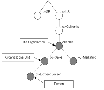
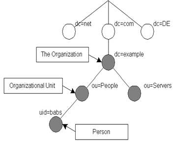
LDAP
defines operations for interrogating and updating a directory. Operations are
provided for adding and deleting an entry from the directory, changing an
existing entry, and changing the name of an entry. Most of the time, LDAP is
used to search for information in the directory. The LDAP search operation
allows some portion of the directory to be searched for entries that match some
criteria specified by a search filter. Information can be
requested from each entry that matches the criteria.
For
example you can easily search an entire directory sub-tree at and below dc=acme,dc=com for people with
the name Hymie
Piffl,
retrieving the email address of each entry found. Or you might want to search
the entries directly below the st=Florida,c=US entry for organizations with the
string Acme in their name and
that have a fax number.
LDIF
The
LDAP Data Interchange Format (LDIF) is used to represent
LDAP entries in a simple text format. (See ldif(5) man page.) The technical specification
for LDIF is RFC-2849. While each LDAP server stores data internally in some
server-specific way, it is possible to export data from one server, to import
into another. LDIF is the standard format used for this, and is supported by
nearly every LDAP application and server (Outlook, Thunderbird, ...).
The
file format may be text but it can be complex and confusing. There are a
number of GUI tools to create LDIF files for you. In addition, there are a
number of (usually Perl) scripts that can create LDIF data files from standard
system files, such as /etc/passwd.
An
LDIF file consists of entries, separated by blank lines. Lines starting with “#” are comment
lines. Each entry starts with the “dn:” of the entry. All attributes are written one per
line. A line that starts with a single space or tab is a continuation
of the previous line (the newline and the one space/tab are removed as if they
weren’t there). The basic form of an LDIF entry is:
dn: distinguished
name
attrdesc: attrvalue
...
The
attrdesc is the name of some attribute for the entry such as objectClass or 1.2.3 (an OID
associated with an attribute type), and may include options (for example cn;lang_en_US or userCertificate;binary).
The
attrvalue may be specified as UTF-8 text, as base64 encoded data, or as
a URI (to provide the location of the attribute value). The exact nature of
the value depends on the definition of the attribute; some are numbers, others
a filename, but most are plain text. Leading spaces (but not tabs) are allowed
and ignored.
Where
it gets tricky is that base64 values are preceded by a double colon, and URIs
are preceded by “:<”. If an attrvalue contains non-printing characters, or
begins with a space, a colon (‘:’), or a less than symbol (‘<’), then you
must use the base64 encoding scheme (and remember the double colon!).
Here is an example showing all three
variations:
# Entry of user bjensen:
dn: cn=Barbara J Jensen,dc=exam
ple,dc=com
cn: Barbara J Jensen
cn: Babs Jensen
objectclass: person
description:< file:///home/bjensen/.plan
sn:
Jensen
jpegPhoto::
/9j/4AAQSkZJRgABAAAAAQABAAD/2wBDABALD
A4MChAODQ4SERATGCgaGBYWGDEjJR0oOjM9PDkzODdASFxOQ
ERXRTc4UG1RV19iZ2hnPk1xeXBkeFxlZ2P/2wBDARESEhgVG
...
Note:
You can pipe (echo or cat) data through the
recode command to convert it to base64:
echo
':starts with a colon' | recode ../Base64
The
DN attribute is a comma-seperated list (like a pathname). If any component of
that contains a comma, you need to escape it with a backslash:
# Entry of user hpiffl:
dn: cn=Hymie Q. Piffl\, Jr.,dc=example,dc=com
cn: Hymie Q. Piffl, Jr.
...
This
covers the basic file format, but each entry can include additional lines that
allow you to use a single LDIF file to change, add, and delete the attributes
of entries, or to delete, rename, and move whole entries.
Components in an LDAP Data Management System:
There
are at least four components in a client-server data management system that
will use LDAP:
1.
A data manager (i.e., the server)
2. A data schema or
collection of schemas that the data manager can support
3. Data or content
that respects the schema and can be loaded into the data manager
4. A client
application that accesses the data
You
need to assemble these elements and configure them all to cooperate with each
other.
LDAP the protocol versus LDAP the server
While
client and server programs can be designed to use LDAP directly, today it is
common to be concerned with security, correctness, robustness, and efficiency.
All of which are hard to program yourself every time you want to develop some
client or server. So instead of talking directly with some server, clients
speak with an intermediary server. The intermediary server is in turn
configured to communicate with various data sources called back-ends.
This intermediary server is also configured to negotiate all session and
security aspects. Such a product is (confusingly) also known as a data
manager.
You
can think of an LDAP data manager as a convenient and consistent front-end view
to a whole range of DMS technologies. Real-world LDAP back-ends use everything
from a network information system (NIS) account registry to conventional
relational database management systems (RDBMSs) such as Informix and DB2.
(Oracle does LDAP directly.) Application programmers can develop e‑mail
projects, corporate directories, course catalogs for colleges, form
repositories, search engines, etc., without concerning themselves about where
the actual information is coming from. User account information may, for
example, come from personnel department files on a mainframe, NIS logins on
engineering workstations, a Windows NT domain controller, or someplace else.
Today
there is a product called OpenLDAP, which is a popular, free, and open
data manager, that speaks to clients using LDAP. OpenLDAP comes with an API
to easily create clients, and it also comes with several command line tools
that can be used in scripts. Here’s an example command line tool that repeats
the search shown earlier:
ldapsearch -h ldap.yahoo.com "&(sn=Pollock)(c=US)"
(GUI
LDAP clients are available: lat,
kldap, phpLDAPadmin, and gq. Most email
clients, including Thunderbird, support LDAP for address book information.)
OpenLDAP
is not a database directly but rather an intermediary that can serve data to
clients from an ever-growing list of database server “back-ends”. With
OpenLDAP you can use nearly any back-end from plain text files to relational
database servers such as MySQL. Note a single OpenLDAP server can serve many
different directories at once, from multiple back-ends.
When
using a data manager such as OpenLDAP on a production system, there are six
components to configure:
1.
The OpenLDAP data manager (i.e., the server, called slapd)
2. A data schema
that the data manager can support
3. A back-end DMS
that actually serves the data
4. Data or content
that respects the schema and can be loaded through the data manager
5. A configured
security layer that OpenLDAP can use
6. A client
application that accesses the data
Configuration:
OpenLDAP is very commonly used on both
Linux and Unix, however it does have a number of limitations and quirks that
make configuration tricky. There is at least one new open source LDAP server
being developed, however it isn’t widely used at this time.
Besides the OpenLDAP client and server
software packages, you’ll need to install several other packages. nss_ldap to support LDAP from the nsswitch.conf mechanism and for PAM,
GUI LDAP tools, LDAP support for PHP, Perl, email, Apache, and other software
without built-in LDAP support.
You
can find all sorts of information about configuration on the web, especially
from OpenLDAP.org.
OpenLDAP
allows you to control the access to the data and the security of the sessions.
It has many settings to permit fine-grained control over how clients can talk
to the sever (negotiation of various session parameters, such as encryption),
who can talk to the sever (client authentication), what data clients can view
(client authorization), and other details. The security configuration is
perhaps the most difficult part of the configuration of OpenLDAP. OpenLDAP
supports a great number of choices for each facet of security, including the
ability to use a SASL (“Simple Authentication and Security
Layer”) library such as the ones from Cyrus or Gnu. SASL
also has complex configuration.
Fortunately,
for development and learning purposes, you can configure your firewall (and/or
TCP Wrappers) to ignore all LDAP requests from anywhere except the localhost.
Then you can ignore (for now) the security settings and concentrate on getting
the server up. This involves several steps:
1.
Make sure your OpenLDAP packages are installed and up to date
2. Make sure your
firewall doesn’t permit external LDAP requests (those coming in to ports 389
[LDAP] and 686 [LDAPS] )
3. Creating a
directory containing a couple of records
4. Configuring
OpenLDAP to serve this directory
5. Configuring
OpenLDAP to run at boot time.
After
this, you use the command line tools to test your service. Use the log files
for (hopefully) helpful error messages if things don’t seem to be working.
Finally add some additional data to your directory and have fun using it. Here
are the detailed steps:
1.
Edit the slapd.conf
configuration file. This file is the configuration file for the OpenLDAP
server and is found in /etc/openldap.
It contains various directives you can un-comment or comment. The start of the
file has global directives, up to the first database type
statement. The directives that follow that apply to that DB. This can be
followed by additional DBs, one for each directory you want to serve. The
global directives you are likely to use are:
o
The include
directives for are for the schema files you will use.
o
You can define the versions of LDAP clients that you will
support.
o
Next are some file locations, the defaults are fine.
o
The moduleload
directives are used to provide support for the type of back end data source you
plan to use if OpenLDAP was compiled for modules. (Not on
Fedora!) Just un-comment the appropriate ones for your DBM.
o
The next section of this file describes the security you plan to
provide. You can use TLS to
encrypt the sessions, and also provide access control to restrict who can do
what with your data. Each part of the LDAP tree can include different access
controls, which may be based on user or location (IP Address).
o
The rest of the file contains one or more database descriptions.
For each you include the DB type (see slapd.backends(5)),
the directory name (and suffix), the password for the administrator (root
distinguished name) of this database (the root password), the directory where
the LDAP server will put its files for this DB, and other DB-specific
information, such as what indexes to maintain and replication information.
Supported backends include SQL (using ODBC), LDIF (plain text files), etc.
Each type has its own man page describing specific directives.
An
example using a Berkeley database file for a back-end might look like this, for
a DB that defines a “Manager” role for employees to assume:
database bdb
suffix "dc=example,dc=com"
rootdn "cn=Manager,dc=example,dc=com"
rootpw secret
directory /var/ldap/example.com-data
You can add access
controls to the data, specifying who is allowed access to what. You can
restrict access to part of the directory (tree), records of a certain type, or
individual attributes (fields) of records. For example:
access to attrs=password;x-hidden by * =cs
restricts all users
to only compare a password, not read it.
(Defining
a rootDN is necessary initially to add any records to the directory. Once
you’ve added some users that can be authenticated and that have the appropriate
permissions, you can remove this entry.)
Note
it may not be the best idea to include a plain text password in this file. It
is also permissible to provide hash of the password in RFC-2307 form. slappasswd may be used to
generate the password hash. For example the command “slappasswd -s secret” results in a
hashed password you can copy into the configuration file:
rootpw {SSHA}ZKKuqbEKJfKSXhUbHG3fG8MDn9j1v4QN
With
the “-h 'scheme'” option you can
use different hash schemes (such as '{MD5}'). While the “‑s” option allows
this command to be scripted, it is not secure to have your password on the
command line (ps listing, .history file). Leave
this out and the program will run interactively, prompting you for the
password.
2. Check ownership and
permissions. The group and user that slapd
runs as is supplied on the command line when starting this tool, not (as one
would expect) in the configuration file. On Red Hat like systems, options for
servers are stored in files named for the service, under /etc/sysconfig. On Fedora, the
default is user and group ldap/ldap. OpenLDAP switches to this
user/group before attempting to read its configuration file. The bottom
line is all files in /etc/openldap/*
must be set to mode 0600 for security, with owner/group of ldap/ldap
(including for the directory itself), or the server will mysteriously fail to
run:
chown -R ldap.ldap /etc/openldap
chmod 600 /etc/openldap/*
chmod 700 /etc/openldap # 755 ok for low-security
This setup will
cause problems on reboot. Newly created DB files may have the wrong
owner. Also, Berkeley DB wants a DB_CONFIG
file (even if empty) or you get a warning. So:
cd /var/lib/ldap; touch
example.com-data/DB_CONFIG
chown -R ldap.ldap . # Do again after running once.
3.
Start slapd.
Check for any error messages in the log files that would indicate a
mis-configuration. Check that the LDAP server is listening on the correct
port. If all seems to be okay, test out the server using a search:
ldapsearch -x -b '' -s base '(objectclass=*)' \

  namingContexts
(Don’t
forget the quotes.) This should return the following:
dn:
namingContexts: dc=example,dc=com
4.
Add some records to the database. The OpenLDAP command line tool
uses the standard “LDIF”
file format to contain data. You create this file using vi (in real life an application
creates the data to add in the correct format, or you can use a special GUI
tool). (See the ldif man
page.) A sample LDIF file (see LDIF-data.txt
resource) might look like this:
dn: dc=example,dc=com
objectclass: dcObject
objectclass: organization
o: Example Company
dc: example
dn: cn=Manager,dc=example,dc=com
objectclass: organizationalRole
cn: Manager
You
can have multiple records defined in one LDIF file, each starting with the “dn:” line (and
separated with a blank line?). The LDIF file entries show data to add, data to
change, or data to delete from the LDAP database, depending on the command line
tool used.
OpenLDAP
supports an extended format documented in the slapd.replog(5) man page. This permits extra
entries such as the “changeType:”
pseudo-attribute, which allows a single data file to contain additions,
modifications, and deletions. This is useful when you need to synchronize a
replica from the change log of the master LDAP server.
If
you don’t say what to do with a “changeType:” line, the default is to add the data if
using the ldapadd tool, and to
modify it if using ldapmodify tool (which is a
hard link to the same program). There is also an ldapdelete command to delete
matching data.
Next
add your data using the ldapadd command. Then repeat the ldapsearch command to see if
the new record is found:
ldapadd -x -D "cn=Manager,dc=example,dc=com" -W \

   -f example.ldif

ldapsearch -x [-LLL] -b 'dc=example,dc=com'
OpenLDAP
tools can use default options to simplify the use of the command line tools,
for example the default base DN to use. These options go in /etc/openldap/ldap.conf file. Do not
confuse this file with /etc/ldap.conf, which is not
part of OpenLDAP at all, but the nss_ldap package (i.e., used to
configure pam_ldap).
Additional considerations
An
LDAP server used for vital services (such as login) must be secure and reliable
as possible. Frequent backups of the data are desirable. However, if the LDAP
server fails for any reason (or the back-end data store), nobody could log into
the network. Accordingly you should deploy an LDAP server with similar
considerations as a DNS server. In this case this means you should replicate
the LDAP server.
A
replica is a second server that serves the same data. This
second server get the current data from the primary server. Unlike a slave DNS
server, which periodically polls the master to check for updates, OpenLDAP runs
a program on the master LDAP server, watching for changes and pushing
the update to the replicas. For OpenLDAP the stand-alone server that does this
is called syncrepl. If deploying a
replica, you must make sure your firewall allows syncrepl to transfer the data work.
If
the master OpenLDAP server fails, clients can look up data from any replica. However,
replicas don’t support updates. Some (commercial) LDAP servers work
differently but OpenLDAP is so common you may want to handle this situation.
The solution is to use clustering technology. For Linux see Linux-HA.org (Highly Available
Linux Project). You first set up a virtual IP address for your
LDAP service. The redirector (or router) uses a form of DNAT to send all LDAP
traffic to the master LDAP server. The replica is unused but is running so
updates from syncrepl are handled.
Another component called the heartbeat monitor checks the master
server continuously, by tracking a type of keep-alive packet sent and
replied to regularly.
If
the heartbeat monitor thinks the master has died, it will switch the virtual IP
address to forward packets to the replica instead. Using some clever
scripting, you can have the replica change its type to master at this point, so
as to accept updates.
When
the original master comes back on-line, it should be brought up as a replica.
Then you can continue to use the current server as the master, or kick the
heartbeat monitor in the head to switch ‘em back to the original
configuration. (This would be useful if the standby hardware wasn’t as
powerful as the main server.)
LDAP Versions and References:
LDAPv1
(RFC-1487) was the first cut at a lightweight X.500 and isn’t used anymore. It
was developed in the early 1990s. (The RFC is historic only.)
LDAPv2
technical specification (RFC-3494) is also historic, but continues to be used
in some places. As most implementations of LDAPv2 do not conform to the LDAPv2
technical specification, interoperability amongst implementations claiming
LDAPv2 support is limited. LDAPv2 also differs significantly from LDAPv3, so
deploying both LDAPv2 and LDAPv3 simultaneously can be quite problematic.
LDAPv2 should be avoided.
LDAPv3
was developed in the late 1990’s to replace LDAPv2. LDAPv3 adds the
following features to LDAP:
·
Strong Authentication via SASL
·
Integrity and Confidentiality Protection via TLS (SSL)
·
Internationalization through the use of Unicode
·
Referrals and Continuations
·
Schema Discovery
·
Extensibility (controls, extended operations, and more)
The
Lightweight Directory Access Protocol version 3 (LDAPv3) was specified by this
set of ten RFCs but is now described in a single RFS, 4510:
|
LDAP RFCs and their descriptions
|
|
RFC2251
|
Lightweight Directory Access
Protocol (v3): The specification of the LDAP on-the-wire protocol
|
|
RFC2252
|
Lightweight Directory Access
Protocol (v3): Attribute Syntax Definitions
|
|
RFC2253
|
Lightweight Directory Access
Protocol (v3): UTF-8 String Representation of
Distinguished Names
|
|
RFC2254
|
The String Representation of
LDAP Search Filters
|
|
RFC2255
|
The LDAP URL
Format
|
|
RFC2256
|
A Summary of the X.500(96)
User Schema for use with LDAPv3
|
|
RFC2829
|
Authentication Methods for
LDAP
|
|
RFC2830
|
Lightweight Directory Access
Protocol (v3): Extension for Transport Layer Security
|
|
RFC3377
|
A list of RFCs for LDAP (v3)
|
|
RFS3771
|
LDAP Intermediate Response
Message [Format]
|
RFCs
may be found at a number of places on the Internet, including www.faqs.org/rfcs/.
See also RFC-2222 (the description of SASL) and Gnu gsasl reference manual
and Cyrus SASL reference manual for information on specific SASL
implementations.
Application Configuration:
Many
applications and servers can be configured to use LDAP instead of their own
files. These include login (you can configure PAM to use LDAP
rather than /etc/passwd, /etc/shadow, and related
files), sendmail (or other MTAs
(email servers), POP and IMAP servers,
Samba, Mozilla/Netscape, various email clients, and many others. By including
the correct schemas (or creating your own), you can avoid duplicating
information needed by several servers (for instance, sendmail and POP can use
the same user list). You also keep all information in a central repository,
which you can more easily replicate than trying to provide such features for
many individual servers. Backups become simpler as well.
Each
application has its own way of using LDAP. Consult the documentation available
for each application you wish to configure. Note that not all applications or
servers today can use LDAP.
To
use LDAP to replace /etc/{passwd,group,shadow,gshadow} files you need to
install the nss_ldap package. This allows you to configure /etc/nsswitch.conf to use LDAP as a
primary source of aliases, ethers, groups, hosts, networks, protocol, users,
RPCs, services, and shadow passwords (instead of or in addition to using flat
files or NIS).
This
package also provides a pam_ldap PAM module you can use with any PAM-ified client.
Interestingly the two don’t work exactly the same way. If you configure nsswitch.conf to use LDAP for
passwords, the standard pam_unix module will use
LDAP. So why do you need pam_ldap
too?
pam_unix will attempt to
fetch (read) the password from the source, /etc/shadow or LDAP. That requires read permission
on the password entry for anonymous users. Not a good idea! Pam_ldap just tries to bind
to the server (that is, log in) without reading anything. It uses the
information from /etc/ldap.conf, not to be
confused with /etc/openldap/ldap.conf (defaults for OpenLDAP
client tools). If the login is successful, the supplied password must be okay.
In
addition, not all PAM-ified applications are supported by nsswitch.conf. Also the pam_unix module doesn’t
handle password changes for LDAP well, or LDAPv2 clients, or some servers, so
you need to configure pam_ldap for that. See
the nss_ldap package
information (rpm ‑qi nss_ldap) for more
details.
Using LDAP for accounts, groups, and
passwords [this needs updating]
[
From en.wikibooks.org/wiki/Linux_Guide/LDAP_authentication_in_Linux, posted
Friday, December 09, 2005 by swapnil_durgade@yahoo.com ]
1.
Make
sure the required packages are installed:
openldap-2.2.23-5.i386.rpm
openldap-clients-2.2.23-5.i386.rpm
openldap-servers-2.2.23-5.i386.rpm
2. Configure
OpenLDAP: Edit
file /etc/openldap/slapd.conf and change at
least these settings:
suffix "dc=example,dc=com"
rootdn "cn=manager,dc=example,dc=com"
rootpw
yourrootpassword
3. Start OpenLDAP: Run the command service ldap start
4.
Use
Migration Script to create ldif files from /etc/passwd and /etc/group:
Edit /usr/share/openldap/migration/migrate_common.ph:
$DEFAULT_MAIL_DOMAIN
= "example.com";
$DEFAULT_BASE
= "dc=example,dc=com";
Create
ldif files
in /root (home) directory
with the following:
./migrate_group.pl
/etc/group ~/group.ldif
./migrate_passwd.pl
/etc/passwd ~/passwd.ldif
./migrate_base.pl
> ~/base.ldif
5.
Import
ldif files into OpenLDAP:
ldapadd
-cx -D "cn=manager,dc=example,dc=com" \
-w yourrootpassword -f ~/base.ldif
ldapadd
-cx -D "cn=manager,dc=example,dc=com" \
-w yourrootpassword -f ~/passwd.ldif
ldapadd
-cx -D "cn=manager,dc=example,dc=com" \
-w yourrootpassword -f ~/group.ldif
6.
Configure
PAM for ldap authentication: Use authconfig (a RH cmd)
On
the first screen select Use
LDAP and Use LDAP Authentication.
On
the next screen, type Server: 127.0.0.1
Base DN: dc=example,dc=com
Or
you can edit the various files in /etc/pam.d directly. Add to system-auth (and/or to other
files):
(To
be determined)
You
may need to edit additional files, such as /etc/libuser.conf, /etc/default/useradd, login.defs, and possibly other files as well.
Fedora
allows nsswitch to use LDAP directly, or via PAM, or via SSSD. PAM can be
configured to use SSSD and vice-versa. The modules don’t authenticate the same
way, and you may need different access rules for your database depending on
which system you plan on using. (This whole issue is a confusing mess in
Fedora as of 2015.)
Other Application Configuration:
Apache
can be configured to use LDAP instead of its htgroup and htpasswd files. See mod_authz_ldap RPM package for
the Apache module you need.
LDAP
and Kerberos can be used together to set up an enterprise scale single
sign-on system, including a mixture of Linux, Unix, and Windows hosts.
LDAP
and an automount daemon are often used together. You store the automount map
files in LDAP, rather than in files on your various file servers.
Solaris
LDAP Notes from docs.sun.com/app/docs/doc/816-4556/6maort2te?a=view
1) BOTH the
posixAccount and shadowAccount are required in the People entries (and your ldif when you use it to add), or
else some error like “Unknown user id” or “invalid credentials” will occur to
login process.
An extra “objectClass: person”
definition will make it more compatible with SUN ONE Console.
2) It is important
that passwordStorageScheme of DS5.2 server is defined as “crypt” using “idsconfig”
or SUN ONE Console, so that legacy passwords from /etc/shadow or NIS gets migrated properly and the login
process has fewer issues.
3) Separate ou=shadow is logically not required as
/etc/passwd and shadow passwords
(/etc/shadow) should all be
stored in the same ou=People
container.
4) The definition
of serviceSearchDescriptor in an LDAP client profile is optional if it
is the default setting as indicated by “man
getent”. Many define the SSDs
explicitly for clarity purposes.
5) The “shadow: files ldap” entry seems to be
an optional entry for Solaris /etc/nsswitch.conf,
but I usually put it there. For Red Hat it seems to be needed.
6) Use the sample pam.conf for pam_ldap provided by Solaris10 system admin guide with
all “pam_unix_cred.so.1” lines
commented out, this version works for telnet/ftp/su/sshd w.r.t. LDAP
authentication.
Lecture 19 — NFS and SMB (Samba)
The main use of networks are to share resources (known as shares),
especially files and printers. Such sharing has many benefits: Reduce local disk
storage and backup requirements, simplifies various sys admin tasks (central
config files, man page repository, ...), eliminates having to merge changes to
files from different copies.
There are many technologies that enable sharing. The choice
depends on the situation, policies and politics, security, and convenience
required. The different scenarios are (note “AS” = Autonomous System):
|
File Sharing Scenario
|
Technology Choices
|
|
User A to share
with self
|
On Same
host
|
—
|
|
Different
hosts, same type, on same AS
|
sFTP, scp,
NFS, sshfs, Samba
|
|
Different
hosts, different types, on same AS
|
sFTP, scp, sshfs,
SMBfs, Samba
|
|
Different
hosts, same type, on different ASs
|
sFTP, scp,
NFS, sshfs, Samba
|
|
Different
hosts, different types, on different ASs
|
sFTP, scp,
SMBfs, sshfs, Samba
|
|
User A to share
with User B
|
On same
host
|
cp, NFS
(insecure), Samba
|
|
Different
hosts, same type, on same AS
|
sFTP, scp,
NFS, sshfs, Samba
|
|
Different
hosts, different types, on same AS
|
sFTP, scp, sshfs,
SMBfs, Samba
|
|
Different
hosts, same type, on different ASs
|
sFTP, scp,
NFS, sshfs, Samba
|
|
Different
hosts, different types, on different ASs
|
sFTP, scp, sshfs,
SMBfs
|
In addition to the technologies shown
above, additional “push” technologies can sometimes be used, including
email and rdist.
gvfs is a
virtual filesystem (but user-space; that is, not built into or supported by the
kernel) for Linux. You will see a “~/.gvfs/”
directory and a bunch of tools “gvfs-*”.
These tools allow you to do things with files on remote systems using a
variety of access protocols including HTTP and SSH. “~/.gvfs” is used to store gvfs mount points. To create a
mount point, use something like this: gvfs‑mount ssh://user@host. (The
mount-point corresponds to “/”
on the remote system in this case.) The newly created mount points can be
accessed with normal tools such as ls
and cat. To see what protocols
(gvfs backends) are available on your system, run the command: ls ‑l /usr/lib/gvfs/gvfsd-*. Without
mounting something first you need to use the gvfs-*
tools to access remote files. For example:
gvfs‑cat http://wpollock.com/index.htm
When sharing files between Unix/Linux
hosts only, NFS is the most popular choice, however SMB may be a better way to
go. When sharing between Windows hosts only, using Windows shares (SMB) is the
way to go.
SMB has an
interesting history; read it at Wikipedia. One version of SMB 1 was renamed CIFS,
but that was not a good protocol. Even a few updates later it was bad.
Eventually, Micorsoft abandoned CIFS and made an entirely new version of SMB,
SMB 2.0. Today SMB 3 is the current version, but for some reason, the name
CIFS is still used sometimes (mistakenly) to refer to the vastly different and
improved SMB.
Sharing printer resources with
Windows clients can’t be done with CUPS, however it can be done with
LPRng (Windows supports LPD protocol). Even email can be used to allow
remote access to printers.
Of all the
choices, two stand out for ease of administration and security: sFTP and scp.
These programs:
·
Require no extra administrative work at all, encrypt file
transfers, and provide user authentication at the remote end. (Standard
Unix/Linux filesystem security provides authorization.)
·
These methods require User A to make sure the file can be
accessed by user B, and usually require User B has an account on both hosts.
This can be difficult to impossible to arrange.
·
Using these methods requires non-transparent access (that is, you
can’t mount the files you want or map a drive letter, and access the
files as if they were local files.
·
These methods don’t allow sharing of printers.
For ease of use two choices stand
out, NFS and SMBfs:
·
You can remotely mount some directory (and all its
contents) locally, and then access the files using pathnames. In Windows, you
can assign a drive letter to the remote share and again access using
pathnames.
·
Products exist to remotely mount Unix/Linux shares under Windows
and Windows shares under Unix/Linux. This is as easy as it gets!
·
There is a conceptual mismatch between Unix and Windows security
models and filesystem attributes (filenames, modes, etc.). As users create and
transfer files from one system to another, some sort of defaults need to be
established, and users must remember that moving a file from one type of system
to another, and back again, may lose attributes.
·
Neither method provides any way to “browse” the network to see
what resources can be shared.
·
SMBfs provides no way to resolve NetBIOS names to IP addresses.
This can be a problem if the Windows-mostly network uses WINS rather than DNS.
Samba addresses many of the problems
with NFS and SMBfs. Samba provides a complete SMB server that clients can use
to access files and printers, browse available resources, and also provides authentication
and authorization services. However Samba opens other security holes and is
more complex to use than NFS or SMBfs.
Solaris 11 includes CIFS support directly, and may not use Samba.
(Or maybe it just includes Samba?) I don’t know if it only supports CIFS or if
it also supports the more modern SMB 2 (or newer).
NFS
Security: NFS and SMB both have
had their share of security woes. NFS in particular was never designed for
security; No encryption is used by default. NFS restricts access to shares
based on the client’s IP address. It then trusts the UID in the access
request from that IP address. So anyone with root access (or a bootable
CD) can “su” to any user ID and
then access any files! It is possible to use Kerberos authentication for NFS.
A useful technique to
security access remote storage volumes would be to run NFS via SSH or SSL
tunnels. However there is a much easier way:
sshfs [user@]host:[dir] mountpoint
[options]
The sshfs software is available from fuse.sourceforge.net.
NFS originally used UDP and RPC, but
now uses a more secure single TCP transport. It still uses some rpc.* services locally. Using
TCPWrappers and identd
(on the client’s host) to restrict access can increase security at the
expense of extra administration overhead. Also using a central authentication
DB (LDAP, NIS+, Kerberos, RADIUS,...) which provides a unique UID per user per
AS can help reduce the UID problem too.
NFS has had three versions so far, 2,
3, and 4. All versions were developed by Sun; for v4 Sun gave control to the
IETF and it is documented in RFC 7530. It is
important that the client and server are using the same version! For Linux, versions
2 and 3 are both called “nfs”
(and are distinguished by an option to specify the version) and version 4 is
known as “nfs4”.
NFS4 is
significantly different from earlier versions. It provides extra security
features, uses a single fixed TCP port (to eliminate RPC use), and locking and
mounting have been integrated into a single protocol. Of course you need the
same version of NFS everywhere (all clients and servers) for it to work. (In
theory, NFSv4 supports earlier versions.)
Unlike earlier versions, NFS v4 only
exports one filesystem per NFS4 server, typically files under /export. To mount other parts of your
server’s files, use the --bind
option of mount on that server,
as in this example:
mkdir -p /export/usr/share
mount --bind /usr/share /export/usr/share
The client then sees “/export” as “serverhost:/” , and “/export/usr/share” as “serverhost:/usr/share”.
NFS is designed to be a stateless
system. When a remote mount request is served, a token called a cookie
is returned (and saved on the client’s disk). File access requests from that
IP that contain the cookie are approved. This scheme means that even if the
NFS server crashes, when it comes back on-line the clients won’t notice any
problems. However statelessness means that file-locking is a difficult
problem, and a file can be modified by two clients at once, thus corrupting the
file.
The good news is that NFS is easy to
work with (without firewalls, if using V3). To mount some NFS share
from a client, you merely issue a mount
command on the client. These can be placed in the fstab file, or monitored with some automounter to be
automatically mounted (a useful solution when you have many mounts, else fstab gets too big).
Here’s an example fstab entry to mount the share foo on system nfsserver at /share/foo
using NFS version 4:
nfsserver:/foo /share/foo nfs4 rw,bg,intr,hard 0 0
Or at the command line:
mount
-t nfs4 -o rw,bg,intr,hard
nfsserver:/foo \
/share/foo
To specify version 2, replace “nfs4” with “nfs” and add the option nfsvers=2. To specify version 3,
change the type to nfs
and add the option nfsvers=3.
(You can also specify nfs v4 similarly.) Note some options are different
between the versions, so consult the nfs
and mount man pages for option details.
Other client-side tasks include
configuring identd, TCPWrappers,
and enabling UDP and TCP ports 111 (for portmap RPC services for versions 2 or 3) and TCP port
2049 (NFS4 port) in the firewall. You may wish to configure an automounter
as well. Some additional utilities you can use include showmount and nfsstat.
On the server
side, NFS is implemented by a number of services (depending on the
version): rpc.lockd and rpc.statd for locking (V3 and
earlier only), rpc.rquotad
for quota enforcement (V3 and earlier only), rpc.mountd
to handle mount and umount requests (all versions), rpc.idmapd (for v4 only, maps user/group names
to/from numbers, but doesn’t use RPC despite the name), and rpc.nfsd (V3 and earlier) or nfs (V4) to handle the actual file
service.
Note, rpc.mountd is used for all versions,
but it is a local (on the server) daemon used by the other server NFS daemons,
and so is not used by clients (at least for V4; not sure about earlier
versions). So dispite the name, it doesn’t need RPC (portmap) running.
All the RPC (remote procedure
call) services depend on another RPC daemon, portmap. However, this isn’t required for V4. (On
Unix systems, the daemons omit the rpc.
prefix.) Other RPC services may be needed for security. Make sure
portmap is not configured to listen to localhost only!
Install the nfs-utils package on
both the server and the client (while not necessary for basic NFS on the client,
it provides some useful features such as locking, and utilities such as showmount).
NFS v3 and
v2 Extra Setup
Besides enabling RPC services for old
versions, open firewall and TCP Wrappers holes (and configure the security
mechanisms is used).
For TCP Wrappers add something like:
#
(IP addresses rather than hostnames *MUST* be
# used for RPC services used by NFS):
portmap: 192.168.0.0/255.255.255.0
lockd: 192.168.0.0/255.255.255.0
rquotad: 192.168.0.0/255.255.255.0
mountd: 192.168.0.0/255.255.255.0
statd: 192.168.0.0/255.255.255.0
Setting up firewall to cover old NFS
port numbers is quite tricky because there are ports that are assigned randomly
as the NFS daemon is restarted. To see what ports you need to open use “rpcinfo -p”, then restart the NFS daemon
with “/etc/init.d/nfs restart” and run “rpcinfo -p” again. You’ll see
that some ports are changed. Each of these daemons can be configured to use a
static port, but the method varies widely between OSes and NFS versions, so
consult the relevasnt man pages. On Fedora use /etc/sysconfig/nfs
and set LOCKD_TCPPORT, RQUOTAD_PORT, STATD_PORT, and MOUNTD_PORT
to (unprivileged, >1024) ports. (Read the RC script to see which variables
to set!) Here is a different Linux system config that uses ports 32764 –
32767:
#
Number of servers to be started up by default
RPCNFSDCOUNT=8
#
Options to pass to rpc.mountd
#
ex. RPCMOUNTDOPTS="-p 32767
RPCMOUNTDOPTS="-p
32767"
#
Options to pass to rpc.statd
#
ex. RPCSTATDOPTS="-p 32765 -o 32766"
RPCSTATDOPTS="-p
32765 -o 32766"
#
OPTIONS to pass to rpc.rquotad
#
ex. RPCRQUOTADOPTS="-p 32764"
RPCRQUOTADOPTS="-p
32764"
Since the rpc.lockd is actually implemented in the kernel, you must
pass options to the code. Use the following kernel
options in grub.conf if lockd is compiled in:
lockd.nlm_udpport=32765
lockd.nlm_tcpport=32765
Use this line in modprobe.conf if lockd is a loadable kernel module:
options
lockd nlm_udpport=32765 nlm_tcpport=32765
Now open firewall holes for all used
NFS ports:
-A
INPUT -p tcp -m state --state NEW --dport 111 \
-j ACCEPT
-A INPUT -p udp -m state --state NEW --dport 111 \
-j ACCEPT
(and repeat for ports 2049 and
32764:32767.)
For NFSv3 and other
RPC services, you can purchase a firewall product (Juniper and others make
these) that can open NFS-related ports automatically. A more portable
technique is to run a shell script as root once NFS has started, which
determines the TCP and UDP ports used for RPC services, and then open the
firewall holes using iptables (on Linux) commands (and adding log entries of
course). With the newer SysV init replacements, you can simply define a new
service that starts whenever NFS does, to open such ports at that time.
NFS v4 Extra
Setup
NFS v4 only uses one fixed port. Just
make a hole for TCP/2049, from the hosts or networks you want to allow access.
Do the same for TCP Wrappers, if used.
NFS Server Setup
Create a directory to be exported as
the NFS filesystem, typically called export,
nfs_shares, or some similar name:
mkdir
/export
chmod a+rwxt /export
A security concern is
that a malicious user might be able to access other files on the same
filesystem. For this reason, it is a best practice to create a new volume (LVM
or partition) and mount it at /export.
Put the sharable content under here. To
share other content, create subdirectories here, then use a bind mount to
export some existing directories without copying them. For example:
umask
022
mkdir -p /export/doc
mount --bind /usr/share/doc/ /export/doc/
mount -o remount,ro /export/doc/
To indicate some directory and all its
contents can be remotely accessed by clients, you must use the exportfs command. You use this
same command to stop sharing.
Th exportfs
command maintains its information in a special file, not human-readable. That
file is read by rpc.mountd to
see what is allowed and with what options. However, an fstab-like file called /etc/exports is used to make
exporting shares easy. Also files in /etc/exports.d/*.exports
are read as well.
The syntax of this file varies a bit
between Unix and Linux (like fstab
and vfstab do) and between NFS
versions. Here is the Linux v4 syntax:
directory-to-share client(option,...)
[client(option,...) ...]
Where client is a hostname ( www or www.foo.com),
a domain-name (*.foo.com), an IP
address (10.1.2.3), or a subnet
address (10.0.0.0/8). (“*” mean any host.) So the above doc
share would have an entry like this:
/export/doc
10.0.0.0/8(ro,async)
Here’s another example, from host docs.wpollock.com:
/export *.wpollock.com(ro,async)
Which would allow any user on any host
in the wpollock.com domain to
mount /export or any subdirectory,
as read-only. You can add additional entries to this file and add restrictions
and different options to each entry. The async
option is faster, but not safe for read-write shares.
After editing the /etc/exports file, either start (or
restart) the nfs service or run exportfs -ra. (Without “-r”, previously exported shares remain
exported; with “-r”, only the
entries in /etc/exports will be
available.)
The client
should allow the required services through the firewall (if you allow all
incoming related/established, outgoing TCP/2049, and incoming 111 for old
versions, you’re fine), be running required RPC services (portmap, and possibly rpc.gssd -m and rpc.idmapd
for v4), and then uses a mount
command similar to the following (assuming the NFS4 server is docs.wpollock.com with a default
domain of wpollock.com):
mount -t nfs4 -o
ro,hard,intr,bg docs:/ /usr/share/docs
or this fstab
entry:
docs:/ /usr/share/docs
nfs4 ro,hard,intr,bg 0 0
(Here, the NFS server name is docs.)
Some commonly used mount and export
options (some legal in exports, some with mount;
see the man page for nfs(5) for
a complete list) include:
rw, ro -
read-write or read-only (for rw,
consider noatime too)
no_subtree_check
- a routine called subtree checking verifies that a file requested from
a client is in the appropriate part of the exported FS. If the entire FS is
exported, disabling this check will speed up transfers.
fsid=0
- identifies the root of the single exported filesystem
bg -
if mount fails, keep trying in the background
hard, soft -
hard blocks until operation succeeds, soft returns error
intr
- allow users to interrupt blocked operations
root_squash
- translate incoming request from UID of 0 to the anonymous user, by default UID
of -2 (often nobody). Use this (the default)!
anonuid=#,
anongid=# - Set the UID and GID of the anonymous user to use during
squashing.
rsize=num
- read num bytes at a time. Default is 1K, 8K is better. There is a
similar wsize also better at 8K. However, if you use the default MTU of 1500,
you still end up sending many packets. It is usually possible to set the MTU
on both the client and server to 9,000 (jumbo packets; not standard but
supported by many hardware vendors).
tcp, proto=tcp
- specify TCP instead of UDP. The exact option depends on which version of NFS
you use (2 or 3; in v4 tcp is
the default).
async,sync - async is faster and old default; sync is safer.
insecure
- allows incoming requests from any port. The default secure requires
ports < 1024. Use secure unless you allow Internet clients.
sec=value
(value is one of none, sys, krb5, krb5i, or krb5p) - use authentication. (If
the server requires it.)
While not a mount option, you can configure various settings
to improve performance:
RPCNFSDCOUNT
is 8 by default, but on a busy server should be adjusted up to 256 (if you have
sufficient RAM to support all that). You can check if you have enough with “grep th
/proc/net/rpc/nfsd”. The first
number is the number of threads. The second number is the number of times that
all threads were in use. (It’s bad to have this number high; zero is best.)
The last 10 values are a histogram showing the number of seconds (until now)
that NFS threads were in use. The first number is how often 10% of your
threads were in use, then 11%-20%, and so on. The last number shows how many
seconds 90% or more of your threads were in use; you need to adjust the number
up if that last value isn’t zero. You can lower the value if the last 2+
values are zero.
subtree_check
is an option in the exports file on the server is an important safety measure
(like squash_root). However, you don’t need it if you only export a separate
filesystem (and not just a subdirectory of an existing filesystem). Turning
this off can increase performance.
NFSTest
is a package of tools that can be used to test NFS setups, both the client and
server side.
For Solaris 10,
NFS4 should be used exclusively. You specify which file systems are to be
shared with the share command or
the /etc/dfs/dfstab file.
Entries in the /etc/dfs/dfstab file are shared automatically whenever
you start NFS server operation. The lines of this file look like this:
share [-F nfs] [-o specific-options]
[-d description] pathname
After editing this file, reboot or run
“shareall” command to update the
list. Then verify the information is correct by running the command “share”. Next, configure autofs to make the shares available to
clients.
To restart NFS after making changes:
svcadm restart
network/nfs/server:default
On the client side, to auto maount an NFS
share at boot time add a link like this to /etc/vfstab:
NFS-server:sharename
- /var/mail nfs - yes rw
(where sharename is a pathname listed
in dfstab.)
From the command
line:
mount -F nfs -o ro bee:/export/share/local
/mnt
Even easier is
to use the automounter that makes such shares available through the /net mount
point. The previous example using /net:
cd
/net/bee/export/share/local
Solaris NFS
allows fail-over when a client mounts and one server isn’t available the
next will be used. Here’s an entry from vfstab:
bee,cee:/export/share/foo - /usr/foo nfs - no ro
For NFS version 3 on
Solaris, you need to open firewall ports for TCP and UDP, for: 111 (rpcbind/portmap),
2049 (NFS protocol), 4045 (lockmgr).
As with Linux, RPC services (mountd,
rquotad, and status for Solaris NFSv3) use random
ports by default. I don’t know if there is any way to lock down those ports by
configuration settings, but you can use the technique mentioned earlier to
determine those ports once NFS is running, and then open the firewall holes.
SMB and Samba
Samba is an SMB (Server Message
Block, briefly named CIFS for the Common Internet File System, and
now renamed back to SMB) server for Unix/Linux platforms, enabling Unix/Linux
hosts to share files and printers with Windows (or other Unix/Linux) clients.
In addition the Samba client tools allow a Unix/Linux platform to browse and
access SMB shares (both file and printer shares). As if that wasn’t
enough Samba can also operate as a Windows primary domain controller
and/or a WINS server, and supports Kerberos authentication (and so uses
AD), name lookups, workgroup and domain membership lookups, and more. (Samba
v4, still in beta as of 8/2012, does operate as an AD.)
CIFS is very complex (due to backward
compatibility and other issues) and provides hundreds of service calls, no
system (not even MS servers!) fully implement them all. SMB since version 2 is
much better: streamlined, modern features and security, and good performance.
Background
NetBIOS started life in 1983, as
an IBM BIOS replacement that sent requests from DOS applications for reading/writing
storage (DOS interrupt 21h), to either to the local disk or across a network
depending on the “disk” named in the request. NetBIOS is thus an API and not
really a protocol; you still needed a network to transport requests and
replies. In the early days there was not IP or Internet, only proprietary
networking protocols and software.
NetBEUI (NetBIOS Enhanced User
Interface) allows added packet format and other protocol matters to NetBIOS,
allowing file requests over a LAN directly. It is thus a link-layer protocol and
sometimes referred to as NBF (NetBIOS frame).
Eventually Ethernet and TCP/IP became
ubiquitous and it was decided to encapsulate NetBEUI packets. This led to NBT
(NetBIOS over TCP/IP, a.k.a., NetBT). The NetBEUI protocol/API makes heavy use
of broadcast messages, which accounts for its reputation as a noisy and
inefficient protocol.
To use NetBEUI, a host running NetBIOS
(NBF) had to resolve a NetBIOS name to a MAC address. With NBT, NetBIOS names
are resolved to IP addresses which then use standard TCP/IP means (e.g., ARP)
to find the MAC address.
Unlike DNS names, NetBIOS names are
not hierarchical and are limited to 15 characters (plus a 16th service
indicator byte). Windows for Workgroups (WfW) added a second level: the workgroup
name. However there is no security; any host can advertise itself as
any NetBIOS name it wants, in any workgroup it wants. Today we use Windows domain
names exactly the same way. (The name Samba comes from: grep 's.*m.*b.*'
/usr/share/dict/words.)
The naming standard to refer to shares is
called UNC (universal naming convention) that looks like this:
\\[workgroup-name\]server-name\share-name
Any host can pick any NetBIOS name it
wants, and to name shares anything too. This means no central DB of names to
manages (i.e., no SA needed) but this makes it impossible to locate a service
unless you already know its name. Name collisions are a problem as well. To
ensure all NetBIOS names are unique each host broadcasts service
announcements and they then resolve any name collisions. You can test
(“ping”-like) NetBIOS name lookups with “nmblookup name”.
NBT provides many options for name
resolution, resulting in fewer broadcasts. These include a name cache, LMHOSTS
lookup HOSTS lookup, WINS query, DNS query, and broadcast. (The “LM” in “lmhosts” stands for LAN Manager,
a popular DOS/OS2-ish OS co-developed by IBM and Microsoft in the late 1980s.)
A browsing feature was added
to all Windows hosts. Each broadcast domain elects a master browser called a WINS
server, which listens for service announcements from all the
hosts advertising NetBIOS names. Client hosts can then just locate the master
browsers (using a protocol similar to ARP) and ask it for a list of shares
available. A redundant WINS server can be configured on a LAN.
Microsoft created a networked file
system service called SMB, which uses the SMB
protocol (service message blocks) that ran on top of NetBIOS and later,
NetBEUI. Microsoft merged the SMB protocol with the LAN Manager product they
had been developing with 3Com, and have been adding features ever since. SMB
is a client-server protocol, unlike NetBEUI which is a peer-to-peer (P2P)
protocol. (Keep in mind, both of these names also apply to the API used by
software to communicate.)
Some of the later features added to SMB
include the ability to run SMB directly on TCP/IP (and not needing NetBEUI at
all), the ability to share printers, NBNS (NetBIOS Name Services, namely
lmhosts and WINS
browsing services, and more recently DNS and LDAP), support for symbolic links
and hard links, support for larger file sizes, share level security
(each share has a password and any user who knows it can access it) and user
level security. At some point, Microsoft renamed SMB to CIFS. That
version of SMB continued to be used until 2006.
Part of the SMB protocol deals with
file services (clients make requests to file servers). Other sections of SMB
the protocol provide inter-process communication (IPC), printing services, and
more. Running multiple services on the single SMB port number causes many
configuration, troubleshooting, and security problems.
The SMB protocol was designed for
single LAN use (it ran on NetBEUI) and security was never a high priority. The
current version runs on TCP/IP directly and can be used across different LANs
or across the Internet, but with a legacy of weak security. MS Windows file
and print sharing across the Internet are thus favorite targets for crooks.
In 2006, MS released SMB
version 2. It reduces the “chattiness” of the SMB 1.0 protocol (a.k.a CIFS) and
reduced the number of commands and subcommands from over a hundred to just
nineteen. It supports pipelining (sending additional requests before
the response to a previous request arrives), improving performance over high
latency links. SMB2 added the ability to compound multiple actions into a
single request, reducing the number of round-trips the client needs to make to
the server. Finally, SMB2 added “durable file handles” (these allow a
connection to an SMB server to survive brief network outages, as are typical in
a wireless network, without having to incur the overhead of re-negotiating a
new session). SMB continues to evolve, with new security and data center
friendly features.
While SMB since
version 2 should not be called CIFS, some still use the old name even when
referring to the newer versions.
SMB servers provide several basic
services:
·
File sharing (and other file services, such as locking)
·
Printer sharing (also sharing of serial ports)
·
Authentication and authorization services
·
NetBIOS name resolution
·
Service browsing
·
Interprocess communications (IPC)
Unix and Linux provide these services
by two daemons, nmbd and smbd. These are part of the Samba
package (samba.org). nmbd handles all NetBIOS naming
and browsing work, and smbd
handles all other tasks (authentication, authorization, and serving shares).
Samba v3 added a third component, winbind. winbind solves the unified logon problem. It uses a UNIX
implementation of Microsoft RPC calls, plus Pluggable Authentication Modules
(PAMs) and the name service switch (NSS) to allow Windows NT domain users to
appear and operate as UNIX users on a UNIX machine.
A winbind
PAM option provides authentication via a Windows domain (either the older
domain or the newer active domain).
A winbind
NSS option allows user identities to be mapped between Windows SIDs and Unix
UIDs and GIDs. For users that don’t have UIDs/GIDs already (i.e., users not in
the /etc/passwd and /etc/group files), winbind uses a DHCP-like solution that
maps the other SIDs to unique UIDs/GIDs is a configured range, and maintains
the database in a file called winbind_idmap.tdb.
To use Active
Directory, the Unix host must run Kerberos 5 (client daemon). (AD is a
compatible variant of Kerberos 5.) Since Kerberos is very sensitive to clock
difference between hosts you should probably run NTP using the same time server
for your Unix host and the AD server.
Once Kerberos is running,
you can “join” your host to the Windows domain.
Modern Samba provides a GUI
configuration interface that works through your web browser called swat (although other tools such as
webmin can be used). Swat is an on-demand service (the
firewall won’t need any adjustment to allow the connection from localhost:901 only, but xinetd or systemd will need to be configured). Note that unlike
NFS, Samba requires no kernel modifications or modules to run.
Update (2013):
The Samba team, lacking any web developers, have dropped swat since they can’t security or
maintain it properly. While you can still find old RPMs for it, they don’t
know about the Samba4 options. Try system-config-samba
instead. (Not as useful as swat,
which would show every option with explanations, but is simple to use.)
There is a swat2
tool available for Samba 4, at samba.org SWAT2, but I
don’t think it is actively maintained (as of 6/2015, the last update was 2013).
Samba
Configuration
Both daemons use the same configuration
file, smb.conf. This “.INI” like file is divided into
sections, and each section contains name
= value
directives. In additional to a few special sections, there is one section per
share.
The special sections include [global] to define overall Samba
parameters, and [homes]
to allow remote access to (local) user’s home directories, without defining
each one separately. This file can be built and maintained with some tool such
as swat or vi. If you do make changes be sure to
keep the older (working) copy around to restore if needed.
You can use the tool testparm to examine your smb.conf file and report any problems.
The minimal configuration includes the workgroup
(or Windows domain) name that you wish your shares to advertise under
(Samba guesses your hostname), and some defined share you can test. (Show
SambaDemo.htm.)
Samba doesn’t
(by default) use PAM or Unix passwords; it has its own user/password DB where
it stores encrypted passwords. (It can be configured to use other DBs, such as
a Wiundow’s AD.) To allow remote user access, you must add entries to this DB
with the smbpasswd
program:
#
smbpasswd -a UserName
You can delete accounts with -x, and
lock/unlock with -d and -e (disable/enable). To configure Samba to use this
DB, configure Samba with:
security
= user
passwd backend = tdbsam
obey pam restrictions = yes
smb passwd file = /etc/samba/passwd_smb
If you specify “security = domain”,
Samba will use Window’s AD. However, such users must also have local *nix
accounts with the same name.
Samba needs a way to resolve NetBIOS
names to IP addresses. There are many schemes possible but the best is to configure
one WINS server per LAN, as shown in the config file below. The Samba host
acting as the WINS server uses the first line shown; all the others use the
second. Each Samba server will advertise its NetBIOS name to the local WINS
server when it comes online.
[At this time Samba WINS won’t
synchronize with MS WINS, so don’t mix ‘em! You really only need one WINS
server per AS, plus a backup. And only for older Windows clients since modern
ones can use DNS name resolution instead, useful if your NetBIOS name is the
same as your DNS host name (note 15 character name limit in NetBIOS). ]
Browsing of Windows shares (also known
as SMB browsing) fails on Most Unix and Linux systems that have a standard
firewall configured. The firewall disrupts the broadcast mode of SMB
browsing, which is the default.
The workaround is to configure a WINS server
on the network with the “wins support” option in smb.conf on that server, and set the “wins server” option in smb.conf
to the IP address of the WINS server in all other hosts (including Windows
hosts). This avoids the need for broadcasts. Opening a firewall hole to allow
the broadcasts is a bad security practice, since your system will believe any
service advertisements it hears!
Share level security means that
remote users don’t have to have valid local accounts. User security is
the default, but doesn’t use Linux accounts either. The smbpasswd file
is maintained with the smbpasswd
command (show). Note it isn’t possible to use /etc/shadow
style passwords for Windows.
Domain level security is used if
you want your server to act as a Windows primary domain controller (PDC). This
requires an smbpasswd entry for each client host and user. (See the -ma option
to add host accounts.)
In addition a PDC requires a “netlogin” share that contains domain
user login script called “login.cmd”
and the group policy file named “config.pol”
(create this with the group policy editor Windows utility):
[netlogin]
comment = Network Logon Service
path = /var/samba/netlogin
guest ok = yes
writable = no
While Samba ships with a large smb.conf file, you only need a few
entries to make working shares:
[global]
netbios name = wpserver
workgroup = CGS2764
oplocks = no
auto services = test *** may not be
needed
wins support = yes ***OR the
following:
wins server = 172.16.1.1
security = share ***OR user
OR domain
[test]
comment = For testing only!
path = /var/samba/test
read only = no
guest ok = yes
browseable = yes
printable = no *** Unless a print share
The default NetBIOS name is the same as
the hostname, by default localhost.
You should set it to a unique value in our class, based on your name.
The guest
ok = yes means no password is required to access this share.
The oplocks
= no parameter disables opportunistic locking by clients. This will
result in significantly poorer performance, but will help ensure that flaky
Windows clients and/or unreliable network hardware will not lead to corrupted
files on the Samba server. The comment string will appear in
network neighborhood and net use output.
You can prevent some files and/or
subdirectories from being shared, by adding “veto
files = /pattern1/pattern2/.../”.
(The patterns are globs.)
See smb.conf man page for all
parameters, especially “encrypt passwords” (defaults to yes), “smb passwd file”
(defaults to /etc/samba/smbpasswd),
“domain logins”, and “logon script”.
You can create your test share with:
mkdir -p -m 1777 /tmp/samba/test
echo 'it works' > /var/samba/test/afile.txt
chmod
444 /var/samba/test/afile.txt
Samba Firewall Configuration
Once you have
your configuration ready (and the shares actually exists and have the correct
permissions), you must then poke some holes in your firewall. The following
ports are used by Samba for SMB networking and SWAT:
·
TCP/135 Used for WINS mgr, MS DNS, MS Exchange, MS RPC
·
UDP/137 Used for NetBIOS network browsing (old name service)
·
UDP/138 Used for NetBIOS datagram service (old SMB)
·
TCP/139 Used for NetBIOS session service (old SMB)
·
TCP/445 Used by NetBIOS over TCP/IP (Win2k & newer: SMB)
·
TCP/901 Used by SWAT (Samba configuration HTTP server)
Not all these
ports are needed in all configurations. If not running WINS you may not need
TCP/135. If not browsing remote shares (say you are using smbmount only) you
don’t need UDP/137:138. Likewise as noted above, you may not need TCP/445 or
TCP/901 (really needed for localhost only, which should already be allowed).
To do this you
can either run the iptables
command with the correct options, or modify the startup firewall rules, then
just restart iptables. The last
few lines of the default /etc/sysconfig/iptables
file looks like this:
-A RH-Firewall-1-INPUT -j REJECT \
--reject-with icmp-host-prohibited
COMMIT
Just above these last two lines, insert
these lines:
-A
RH-Firewall-1-INPUT -m state --state NEW \
-m udp -p udp --dport 137 -j ACCEPT
-A
RH-Firewall-1-INPUT -m state --state NEW \
-m udp -p udp --dport 138 -j ACCEPT
-A
RH-Firewall-1-INPUT -m state --state NEW \
-m tcp -p tcp --dport 135 -j ACCEPT
-A
RH-Firewall-1-INPUT -m state --state NEW \
-m tcp -p tcp --dport 139 -j ACCEPT
-A
RH-Firewall-1-INPUT -m state --state NEW \
-m tcp -p tcp --dport 445 -j ACCEPT
An additional hole from TCP/515 may be
needed to accept print jobs from LPD clients, and/or TCP/631 for CUPS (shown
below):
-A
RH-Firewall-1-INPUT -p tcp -s printer-IP \
--sport 631 -j ACCEPT
Future versions of iptables may include SMB modules, to
allow SMB traffic only on these ports, and not allow any old packet. If
possible restrict access to certain IP addresses only.
(Don’t forget to add rules to ip6tables
as well.)
To use SWAT, it must be started
on-demand (via xinetd) and
allowed only from the localhost. Here’s a sample /etc/xinetd.d/swat conf file:
# default: off
# description: SWAT is the Samba Web Admin Tool. Use \
# swat to configure your Samba server. To use SWAT, \
# connect to port 901 with your favorite web browser.
service swat
{
port = 901
socket_type = stream
wait = no
only_from = localhost
user = root
server = /usr/sbin/swat
log_on_failure += USERID
disable = no
}
Finally you need to start the Samba
daemons. This can be done from the cmd line using the “-D” option to the commands, by creating some xinetd.d config file so the server
starts on demand, or by /etc/init.d/smb
start command (and then
configuring to start automatically at boot time).
When done, you can test your server
with:
smbclient
-L wpollock -U%
which lists the services (“-L”) of local SMB server. “‑Uusername%password” prevents
Samba from prompting you for a password, which isn’t needed here. (If you
leave this out and get prompted, enter a null password by just hitting enter.)
Next try: smbclient //wpollock/test -U%
This should start the FTP-like
interface that allows you to examine, copy, etc. files. Notice the UNC
(Universal naming convention) name contains the NetBIOS name of the
server followed by the share name, and doesn’t list the workgroup name.
A Windows client should show the
available shares in network neighborhood. Besides smbclient, some Linux
GUI tools are smb4k (KDE only), LinNeighborhood, Konqueror
or Nautilus (use “smb://”
in address bar).
Sharing Printing
Samba 3 and
newer are compiled with CUPS support, making sharing your CUPS printers easy.
First define a printer (and enable CUPS if needed). Then modify your smb.conf file by adding:
[global]
load printers = yes
printing = cups
printcap name = cups
auto services = list of printers
[printers]
comment = All Printers
path = /var/spool/samba
browseable = no
use client driver = Yes
public = yes
guest ok = yes
writable = no
printable = yes
printer admin = root
That’s it if the clients have the
proper printer drivers already.
load
printers = yes will automatically create shares for any printers cups
knows about when samba initializes. You usually want this unless you have
printers you don’t want samba to share. Otherwise you need to define
individual print shares, each with printable
= yes.
The path specified in [printers] is used as a spool
directory for the windows jobs as they are being received by Samba. If you
have no preference, use /tmp.
You also might want to consider setting
printer admin so that user can
manage print queues and cancel/pause other people’s print jobs.
In /etc/cups/mime.convs,
you may have to uncomment the:
application/octet-stream application/vnd.cups-raw 0 -
line, and in /etc/cups/mime.types uncomment:
application/octet-stream
These windows
printers don’t even have to be supported by a cups
PPD file, samba can just push a print job already generated by a windows
clients directly to a printer. Of course this won’t work if you need to run a
print filter on your print server first, it only works if the Windows
application generates the correct output (e.g., PostScript). The
application/octet-stream (raw) allows users to send print jobs to the printer
without any cups processing/intervention (which CUPS default installation
disables for security).
If you wish to
allow Windows clients to point and click through the Add-A-Printer dialog,
you must provide the Windows print drivers for your printers. This is done by changes
the “use client driver”
value to “no”, and adding the
following section:
[print$]
comment = Printer Drivers
path = /etc/samba/drivers
browseable = yes
guest ok = no
read only = yes
write list = root
You also need to actually download
and install the printer drivers! You get them from: ftp://ftp2.easysw.com/pub/cups/windows/. These drivers
work on NT, 2000, and XP. You need drivers from Adobe for Win95, 98, and ME;
this is not discussed here. Then do the following to install them:
# mkdir /tmp/cups-samba; cd /tmp/cups-samba
# mv ~/ cups-samba-version.tar.gz
.
# tar
xvzf cups-samba-version.tar.gz
# ./cups-samba.install
# cupsaddsmb -v -H localhost -U root -a
To find out what printer drivers you have installed
use:
#
rpcclient serverName -U 'user%passwd' \

     -c 'enumdrivers'
To delete an old printer driver, try
something like:
#
rpcclient [server name] -U 'user%passwd' \

     -c 'deldriver printerDriver'
Then remove the files related to the
printer in the driver directory. Finally reload/restart CUPS and Samba. Now
Windows users can install print drivers easily by opening “Run...”, entering “\\servername”, and
double-clicking on the printer to install.
Sharing home directories:
[global]
invalid users = root bin daemon adm sync
shutdown \
halt mail news uucp operator
[homes]
browsable = no
writable = yes
How to mount a remote SMB shared directory locally: Smbfs
and cifs are Linux kernel modules you can load that implement the file
sharing portion of SMB.
mount
-t smbfs -o username=username,password=password \
//servername/exportdir /mnt/test
Sample /etc/swf/smb.conf for Solaris10:
(Workgroups must be set the same.):
# Global parameters
[global]
workgroup = WORKGROUP
server string = main-t2
security = user
socket options = TCP_NODELAY
interfaces = 192.168.0.5/24
encrypt passwords = Yes
log file = /var/log/smbd.%m
max log size = 50
time server = No
preferred master = False
domain master = False
hosts allow = 192.168.0.
os level = 55
[homes]
comment = Home Directories
read only = No
nt acl support = No
[u01]
path = /u01
read only = No
Lecture 20 — Wi-Fi
Wireless networking is not new, but
previously was mostly used for point-to-point WAN links. Wireless networking
is common now for workstations, which today are often laptops and notebook (and
PDA and smart phones) computers.
Initially wireless LANs or WLANs
were slow, expensive, proprietary, and not reliable. The IEEE formed a work
group to define wireless standards that would work better and across different vendor’s
products. These standards are known as “802.11”.
There are a number of variations of
this, 802.11a thru 802.11n (and beyond). By far the most common was 802.11b,
commonly known as “Wi-Fi” (or (“WiFi”). Other common standards
included 802.11g and a. These are all sometimes referred to as Wi-Fi. Today
(2012), 802.11n is the most common. The newest standard is 802.11ac, which
should be compatible with 802.11n equipment. 802.11ac potentially operates at
higher data rates, with more reliable and efficient connections. Even newer
standards are in the works.
Due to severe security
flaws in the design of early Wi-Fi standards, the IEEE took 6 years to define a
new standard, 802.11n, ratified in 9/2009. This standard features high
security, greater reliability, much higher throughput, and longer range than
previous versions.
Wi-Fi (b, g and n) transmission is
at the 2.4 GHz band. (802.11n can also use the 5 GHz band.) This is a
commonly used band and thus there is a lot of interference from other devices:
cell phones, garage-door openers, microwave ovens, etc. The 2.4 GHz Wi-Fi band
(b and g) in the U.S. is divided into 14 channels, but they overlap. For
802.11b and g, you need a wide space (one or 2 channel’s worth) between used
channels. (This is a matter of law, and various around the world.) Only
three of the channels can be used simultaneously in a single area. So you
are limited in how many WAPs can be used in one place. Typical transmit power
is 10-20 mW.
The 5 GHz band is divided into many
more channels, so many more WAPs can be used in one place (23 as opposed to
just 3). (See Wikipedia on WLAN Channels.)
Qu: in a single location, how many
different Wi-Fi networks can function at once at the same location? Ans: 3,
but more for 802.11n and newer. Qu: in a single location, how many devices can
operate at the same time? Ans: it depends; with a MAC address on each packet,
multiple clients can share the same channel. As more users transmit,
collisions occur more often. At some point, the channel is swamped and
applications start timing-out. Typically, you run out of bandwidth after
16-32, but that depends on the data rates of the clients (streaming music or
video greatly limits the number of users). Some vendors claim over 100 users,
but I suspect that might be measured using “ping” packets only.
With WiFi, there are
a total of four protocols commonly in use today (2013): a, b, g, and n; and two
frequency bands: 2.4GHz and 5GHz. WiFi b and g use the 2.4GHz area of the
spectrum only. This band provides decent range, penetration, and omni-directionality
(a single antenna provides good signal in three dimensions), but is prone to
interference from other devices; today many, many devices use this band. If
you live in a dense urban environment, it’s possible to end up with so many
WiFi devices trying to find space in this area of the spectrum, that your
router may end up dropping connections.
The alternative
frequencies at 5GHz (used for a and n) are much less prone to
interference, and are (currently, at least) a lot less crowded. There is some
trade off here, as antenna designs make a big difference in terms of how the
5GHz signal propagates away from the router. A cheap 802.11n router uses this
band exclusively; a dual-band device can use either or both bands.
While the 5 GHz band allows 802.11n to
use 23 channels without serious interference, the high speed of 802.11n is
achieve by using two adjacent channels bonded together. (I think that means
that if you add a twelfth WAP in one area, they all switch to 1/2 speed, or
maybe you will need to configure that.)
The new (2013) 802.11ac standard should
support more clients than earlier standards, in part because they use the
available bandwidth more efficiently, and in part due to advances in antennas
(MIMO and beamforming).
WAPs,
antenna types, and placement [Some material from David Liang, “Wireless
Means Radio”, ;login: April 2013 issue]
The “hub” of a Wi-Fi WLAN is called a
WAP (or AP) for wireless access point. This device operates as
the WLAN equivalent of a hub, and contains an Ethernet connection to a server.
All the wireless NICs in the area establish communication sessions with a WAP,
forming the WLAN. The exact area of the WLAN is determined by the power and
type of antennas used by the WAP and NIC. Generally, Wi-Fi is good for
about 30 to 300 meters. You can fine-tune this area by disabling one
antenna, replacing the antenna(s) with directional ones, or fine-tuning the
power used by the WAP (4mw can be good in a crowded location).
Generally, if you plan on having a WAP
cover an area with a radius of 50 feet, you won’t want any other WAPs within
200 feet using the same band, or they can interfere with each other. Note that
all WAPs in the same overlapping area should use the same power levels; it
makes communications worse if WAP A can hear WAB B, but B can’t hear A.
The placement of the WAP is the first
issue the admin must deal with. Ideally, it should be near the center of the
area to be covered, and as far from streets and neighbors as possible. Use the
features of the room to limit the coverage area. (For example, movable room
dividers often contain metal wire inside. Placing the WAP low, say 3-6 feet
off the ground, will allow crowds of people to dampen the signals.)
Suppose you place 3 WAPs in three
rooms, spaced nicely apart. This will cause a problem called “hidden
transmitter”. While the WAP in the middle can hear, and negotiate channel use
with, the outside WAPs, the outside ones can’t hear each other. If they both
start transmitting at the same time, the middle WAP will be confused, causing
many re-transmits (in Ethernet terms, collisions). Ideally, I suppose
you should try to arrange three WAPs in a triangle (remember, only 3 in a
single area are possible).
Of course, the main point of WLANs is not
to have to run lots of wire in your home, and you may live in an apartment with
streets and neighbors all around, so you may have to place the WAP in a less
desirable location. Since the WAPs need to be powered and physically connected
to the network, the location of power and network outlets plays a factor. (Consider
using directional antennas, setting the power lower, or turning off one or more
antennas, to reduce the WLAN coverage area.)
Configuring
WLANs (Wi-Fi)
All the Linux wireless commands start
with “iw”. The two most used
are iwconfig, which handles
802.11b/a/g/n parameters, and iwpriv,
which handles the rest. Note that standard TCP/IP parameters are still set
using ifconfig.
iwconfig
interface options, where options include:
·
essid name
(name of the WLAN)
·
nwid name
(network ID or BSSID, needed for ad-hoc WLANs)
·
freq num
(the frequency to use, in Hertz (e.g., 2500000000 or 2.5G)
·
mode mode
(where mode is one of: Ad-Hoc, Managed, Master, Repeater, Secondary,
Monitor, or Auto)
·
ap mac-addr
the MAC address of the WAP to use
·
key key
(The encryption key, in hex (“1234-4321-09ac”)
or as a string (“s:secret”)
iwpriv
Lists other commands supported by NIC, such as WPA modes.
(See also “man wireless”,
and the commands iwgetid, iwlist, iwspy,
and iwevent.)
iwconfig
wlan0 essid mylan
iwconfig wlan0 mode Managed
iwconfig wlan0 key xxxxxxxx
ifconfig wlan0 10.0.0.10 netmask 255.255.255.0 up
Or, on a RH like system, you can just
create an interface config file in /etc/sysconfig/network‑scripts
with a name such as ifcfg‑wlan0
(see sysconfig.txt for more
options):
DEVICE=wlan0
HWADDR=00:11:50:8e:ee:a9
ONBOOT=yes
BOOTPROTO=none
TYPE=Wireless
MODE=Managed
ESSID=mylan # Default is "any"
SECURITYMODE=[on|off|open|restricted]
RATE=54Mb/s
GATEWAY=10.0.0.1
NETMASK=255.255.255.0
DHCP_HOSTNAME=whoopie
IPADDR=10.0.0.10
IPV6INIT=no
One feature of
wireless, is that various parameters depend on what country you are currently
in. On Linux, the command crda
is used by udev when starting or initializing, or otherwise when a possible
change of country has occured, to set various wireless parameters according to
known regulatory requirements.
On a modern Linux system running
NetworkManager, you can use nmcli or some GUI tools to manage your wi-fi
connections:
nmcli dev wifi list # show
available WAPs
(See the Fedora
22 Network Guide for more information.)
Configuring
WAPs
It pays to use one network ID (SSID)
for each band (2.4 or 5 GHz), rather than one per WAP (as is common). As
user’s roam and other WAPs get used they won’t have to configure their devices
with new SSIDs. For example, if you turn on your tablet to HCC24 or HCC5, you
won’t get pop-ups about network connections lost, and having to select another
network to connect with. (Devices will connect to the strongest signal for a
given SSID.)
Another good idea is to configure a
central DHCP server for all WAPs at a given location. Then when a user roams
to a different WAP, they won’t need a new IP address.
You should enable wireless
isolation, if available. Wireless isolation, sometimes called client
isolation, is a setting on a many WAPs. While the exact meaning varies with
the manufacturer, turn this on to prevent a computer that is connected to a WAP
from connecting to another wirelessly connected device (in the same area, of
course). This is a security measure that prevents users with mobile devices
from by-passing firewalls: normally, a WAP acts like a hub or switch, connected
WiFi devices with a router someplace. When isolated, the MAC address of an
incoming packet is checked, and if it comes from the WiFi side, it won’t be
forwarded except to the router.
Modern WiFi protocols use a fast mode
to send more data in less time. This mode is more sensitive to interference
however. If interference is detected, a WAP will shift into one of the older,
slower modes. This causes interesting behavior in a crowded area: As more
traffic takes place, everything works fine until a certain point when all the
collisions are detected as interference. Then the WAP shifts into slow mode at
the worst possible moment, suddenly overwhelming the available bandwidth. Some
WAPs have a setting that can prevent the mode switch.
Another way to help is to only use the
802.11n (and not b or g). This is because 802.11n need less separation in the
2.4 GHz band, so 4 channels could be used instead of 3. Encouraging users to
use the 5 GHz band by default helps too. That band is inherently less prone to
interference.
Anther setting on a WAP to consider
including, is increasing the beaconing interval to just once every few seconds
(the default is usually a few milliseconds). That will decrease the traffic
and collisions.
Identify
your card
Let’s assume you already have a
wireless card plugged in your PC and want to know which one it is and which
driver you need. Linux has usually a way to display a card identification, but
this depend on the type of card.
If the card is an ISA card, you are
usually out of luck.
If the card is a true PCMCIA or Cardbus
card, you need to use the command
cardctl
ident
to display the card identification
strings. Note that cardmgr will
also write some identification strings in the message logs (/var/log/daemon.log) that may be
different from the real card identification strings.
If the card is a PCI card, you need to
use the command “lspci -v” to display the card
identification strings.
If the hardware is a USB dongle, you
usually get the identification strings from the kernel log using “dmesg” (or in /var/log/messages).
The card identification usually helps
to identify the chipset inside the hardware, and in some other cases it does
not, because the vendor has changed the identity. Once you have identified the
chipset, it is usually straightforward to check if the hardware is supported
and which driver to use.
Most Linux drivers know about some of
those card identifications, and will automatically bind to the hardware. It is
usually simple to add new identification to a driver.
Jacek Pliszka recommends getting the
FCC-ID written at the back of the hardware, and to run it through the FCC database.
He also recommends checking the Windows driver (both identification and file
name) for some clues.
For drivers compiled as modules (but
which are not for removable devices), the parameter interface is flexible and
each driver may be different, so you must look in the documentation.
Basically, the driver defines a set of parameters by their name, and you may
set an array for each keyword (one value for each instance of the hardware).
The module configuration is usually done in
/etc/modprobe.conf like this:
alias
eth1 hp100
alias eth2 wavelan
options wavelan io=0x3E0,0x390 name=eth2,eth3 irq=10,11
NDISwrapper is
Linux software that can translate between Windows32 driver API and the Linux
API. It was designed for NICs and Wi-Fi cards that lack Linux drivers. You
simply install a (legal copy of a) Windows driver (a pair of files, foo.sys
and foo.inf) and use ndiswrapper build a kernel module from it that you can
load. The actual LKM is called ndiswrapper.ko,
which is configured to load the windows driver. Since Windows drivers are
notorious for bypassing the Win32 API, this won’t always work, but is worth a
try if you can’t find a Linux/Unix driver.
Note: A
Windows driver may be shipped with the card. If that is a .exe file, try opening that .exe file with unzip. If a .cab file, use cabextract (yum install
cabextract). Some driver.exe files after extracting will
give “InstallShield” files, usually in a “data2.cab”
file. To extract files out of that InstallShield data2.cab, run “unshield
x data2.cab”
(yum install unshield).
To Install and Use,
get foo.inf and foo.sys in the current directory, then:
yum install --enablerepo=livna
kmod-ndiswrapper
ndiswrapper ‑i foo.inf
# creates module
ndiswrapper -m # adds conf info
to /etc/modprobe.d/ndiswrapper
For PCMCIA modules, the configuration
is usually done in the PCMCIA scripts in the directory /etc/pcmcia/, and you should check
the PCMCIA Howto for details. Note that some distributions may use the HotPlug
scripts. Usually, you don’t need extra driver parameters, as PCMCIA is
Plug-and-Play, and all driver part of the PCMCIA package are already
preconfigured for proper auto-loading. However, you need to make sure the PCMCIA
subsystem load the driver you desire, if there are multiple drivers bound to
the same device you may end up with an unexpected driver. In this case, you
need to edit the various PCMCIA config files (in /etc/pcmcia/
— grep is your friend).
For USB modules, you may use the HotPlug
scripts. USB usually don’t require any driver parameters, but again, you
need to make sure the proper driver is loaded.
Before following up with the wireless
configuration, you may want to make sure the driver is properly loaded,
recognizes the hardware, and can initialize it. This can be done by checking
the message logs (with dmesg).
The Linux kernel 2.6.17 includes
built-in driver support for the Broadcom 43xx based wireless card family. This
Wi-Fi chip family is found in many laptops such as many models from Acer, Apple
(those using Airport Extreme), Compaq, and Dell. This driver support depends
upon another new enhancement to the kernel, the addition of a Softmac layer in
the wireless stack. Softmac is a software MAC (machine access control) layer
that works with Linux’s built-in 802.11 layer. This provides a great deal of
Wi-Fi protocol management features for chips that don’t handle these details in
hardware.
Linux’s wireless improvements also
include support for Cisco’s LEAP (Lightweight Extensible Authentication
Protocol). LEAP is used in Cisco’s and other vendors’ wireless devices,
including clients, switches, access points, and RADIUS servers that use 802.1X
authentication. In turn, this enables network administrators to set up easily dynamic
per-user, per-session WEP (Wired Equivalent Privacy) secured sessions. The
bottom line is that it is easier to use Linux systems in LEAP-secured networks,
although LEAP isn’t very secure.
Solaris
Wi-Fi
First thing to do is to determine the
driver needed. This is usually defined by the chipset in your NIC and
not the vendor’s name, as well as your platform (SPARC, IA32,
etc.). You can find drivers and other information at www.opensolaris.org/os/community/laptop/wireless/. If
there isn’t a Solaris driver for your card, you can try the Solaris version of
the NDISWrapper (ndis). Obtain
it from the above link (.../ndis).
The configuration commands are similar
to the Linux ones. Use ifconfig
to plumb and then configure TCP/IP settings for your Wi-Fi NIC. Use wificonfig for Wi-Fi specific
parameters. The current version doesn’t support WPA configuration so use wpa_supplicant for that.
Wi-Fi
security measures
·
Only use 802.11n or newer standards.
·
Turn off broadcast of SSID (beaconing).
·
Change default SSIDs (names).
·
Disable SNMP on your WAPs (or at least change the default
community strings).
·
Use WPA2 only; older security methods are worthless: WEP, WPA.
·
If using WPA, configuring it to use the maximum WEP key length
available.
·
If using WPA, configure a different default WEP key on different
devices.
·
If using PSK mode, use a strong password.
·
Connect WAPs in separate LANs, outside of the secured intranet.
·
Use captive portals for publicly accessible WLANs.
·
Use VPNs if possible, or SSH/SSL tunnels.
·
War-walk through your company irregularly (no fixed
schedule!) to catch rogue hot-spots.
·
Install/activate personal firewalls on all laptops or other
computers.
802.11n [From: www.cisco.com/en/US/prod/collateral/wireless/ps5678/ps6973/
ps8382/prod_brochure0900aecd806b8a92_ns767_Networking_Solutions_Bro
chure.html]
Current wireless solutions operate in
the 2.4-GHz radio frequency band (802.11g and 802.11b) or the 5-GHz radio band
(802.11a.). Solutions based on the 802.11n standard operate in the 2.4-GHz,
the 5-GHz radio band, or both bands, offering backward compatibility with
preexisting 802.11a/b/g deployments.
Using several new technologies 802.11n
can higher achieve reliability and data rates of 300 Mbps, much greater than
the maximum of 54 Mbps available with 802.11a/g. It is also able to transfer
data over distances of 90m (300ft) indoors, double that of those previous
technologies.
One Feature is the use of MIMO
(multiple input, multiple output). 802.11a/b/g wireless access points and
clients communicate through a single spatial stream over a single antenna. With
MIMO, 802.11n access points and clients transmit two or more spatial streams,
and employ multiple receive antennas and advanced signal processing to recover
the multiple transmitted data streams. MIMO-enabled access points use spatial
multiplexing to transmit different bits of a message over separate antennas,
providing much greater data throughput and allowing for more robust, resilient wireless
LANs. Whereas previous wireless technologies had problems dealing with signal
reflections, MIMO actually uses these reflections to increase the range and
reduce “dead spots” in the wireless coverage area.
The most straightforward way to
increase the capacity of a network is to increase the operating bandwidth. However,
conventional wireless technologies are limited to transmitting over one of
several 20-MHz channels. 802.11n networks employ a technique called channel
bonding to combine two adjacent 20-MHz channels into a single 40-MHz
channel. The technique more than doubles the channel bandwidth. Channel
bonding is most effective in the 5-GHz frequency given the far greater number
of available channels. (The 2.4-GHz frequency has only 3 non-overlapping
20-MHz channels.)
Packet aggregation: In
conventional wireless transmission methods, the amount of channel access
overhead required to transmit each packet is fixed, regardless of the size of
the packet itself. As data rates increase, the time required to transmit each
packet shrinks, but the overhead cost remains the same, potentially becoming
much greater than the packet itself at the high speeds delivered with 802.11n.
802.11n technologies increase
efficiency by combining multiple packets of application data into a single
transmission frame. In this way, 802.11n networks can send multiple data
packets with the fixed overhead cost of just a single frame. Packet
aggregation is more beneficial for certain types of applications such as file transfers
due to the ability to aggregate packet content. However, real-time
applications (e.g. voice) do not benefit specifically from packet aggregation;
waiting until you had the next packet would cause latency (delay).
WiMAX and
LTE
WiMAX is a wireless digital
communications system, also known as IEEE 802.16 or 3G wireless (also
called “4G”), which is intended for wireless metropolitan area networks
(MAN). WiMAX can provide broadband wireless access (BWA) up to
30 miles (50 km) for fixed stations (802.16d), and 3 to 10 miles (5 to 15 km)
for mobile stations (802.16e). In contrast, the Wi-Fi/802.11 wireless local
area network standard is limited (in most cases) to only 100–300 feet
(30–100m).
In spite of the head start, WiMAX is a
dead technology. The new 4G winner is LTE, or long term evolution.
This has many advantages over WiMAX and other 4G proposed technology, including
efficient use of radio spectrum and significantly faster speeds (up to 100
MiB/sec, but currently 10 MiB/sec is common).
Li-Fi
While not yet (2014) a standard, Using
LEDs and photodetector has some advantages over other wireless technologies, in
some cases. Light won’t interfere with airplane electronics, and is unaffected
by EMI/RFI. It can support more than 10 times the throughput of current Wi-Fi,
and has hundreds of times shorter latancy. It may also be cheaper (and take
far less energy). Furthermore, as LED lightbulbs become common, a small/cheap
amout of circuitry can be added to make each lamp a Li-Fi hot-spot.
However, light won’t reach as far as
Wi-Fi, and is only good for 1 to 10 meters currently. Although standards are
lacking so far for this new tech, there are some in the works, including IEEE-802.15.7
(VLC, for visible light communications).
Lecture 21 — Overview of Kerberos
[ Adapted from:
www.isi.edu/gost/brian/security/kerberos.html, “The Moron’s Guide to Kerberos”,
www.kerberos.org, and
from Sun Solaris docs: docs.sun.com/app/docs/doc/816-4557/?a=view ]
Kerberos is a network
authentication protocol, originally developed for MIT’s Project Athena in
the 1980s. Today it has become the most widely deployed system for
authentication and authorization in modern computer networks (in part because
Window Active Directory is a variant of Kerberos). Currently it is
mostly used in large corporate networks. Kerberos’ ability to require strong
mutual authentication has enormous potential to protect consumers doing
business on the public Internet from phishing and other types of attacks. The
current version is 5 (but you may still find v4 in use), which can
inter-operate with a Window’s AD.
Kerberos can be considered as an
authentication service. Its purpose is to allow users and services to authenticate
themselves to each other. That is, it allows them to demonstrate their
identity to each other. The role of the Kerberos server is as a trusted third
party in this process.
Kerberos was designed to eliminate the
need to demonstrate possession of private or secret information (the password)
by divulging the information itself. Kerberos is based on the key distribution
model developed by Needham and Schroeder. A key is used to encrypt and decrypt
short messages. Keys provide the basis for the authentication in Kerberos.
The Kerberos service is a
client-server architecture that provides secure transactions over
networks. The service offers strong user authentication, as well as integrity
and privacy. Authentication guarantees that the identities of both the sender
and the recipient of a network transaction are true. The service can also
verify the validity of data being passed back and forth (integrity) and encrypt
the data during transmission (privacy). Using the Kerberos service, you can log
in to other machines, execute commands, exchange data, and transfer files
securely. Additionally, the service provides authorization services, which
allows administrators to restrict access to services and machines. Moreover,
as a Kerberos user, you can regulate other people’s access to your account.
The Kerberos service is a
single-sign-on system, which means that you only need to authenticate
yourself to the service once per session, and all subsequent transactions
during the session are automatically secured. After the service has
authenticated you, you do not need to authenticate yourself every time you use
a Kerberos-based command such as ftp or rsh, or to access data on an NFS file
system. Thus, you do not have to send your password over the network, where it
can be intercepted, each time you use these services.
Qu: How do you authenticate yourself
in real life? Typically, you show your driver’s license (or ID card, if
you’re not of driving age) when requesting a restricted service (e.g., getting
a drink, watching an ‘R’ rated movie, ...). This ID shows that there is an agency
(the one that issued the license or card) that has linked a given identity to a
physical likeness. This physical likeness usually consists of a photo and some
physical stats, and is considered difficult to copy. (That is, you can’t
change yourself to look like someone else, without detection.)
The identity consists of
a name and an address, and some other information, such as a birth date. In
addition, there may be some restrictions on what the named person can
do: they may be required to wear corrective lenses while driving. (In many
cases, this restriction is implicit: one can’t drink until the age of 21, based
on the birth date on the card.) Finally, the identification has a limited
lifetime, represented by the expiration date on the card.
Kerberos works in basically the same
way. It’s typically used when a user on a network is attempting to make use of
a network service (such as a network printer), and the service wants assurance
that the user is who he says he is. The user presents a ticket
that is issued by the Kerberos authentication server (AS), much
as a driver’s license is issued by the DMV. The service then examines the
ticket to verify the identity of the user. If all checks out, then the user is
accepted.
Kerberos
Sessions — A Simplified View
A client (a user, or a service such as
NFS) begins a Kerberos session by requesting a ticket-granting ticket (TGT)
from the Key Distribution Center (KDC). This request is often
done automatically by login.
The KDC creates a TGT and sends it back
in an encrypted form to the client. The client decrypts the ticket-granting ticket
by using the client’s password.
Now in possession of a valid
ticket-granting ticket, the client can request tickets from the KDC for all
sorts of network operations, such as rlogin, FTP, or CUPS, for as long as the
ticket-granting ticket lasts. This ticket usually lasts for a few hours.
To access some service, the client
software (e.g., SSH, FTP, NFS, Samba, ...) requests a ticket for a particular
service (for example to remote login on another host) from the KDC. The client
software sends the KDC the user’s TGT as proof of identity. After validating
the TGT, the KDC sends a ticket for the requested service back to the client
software. The client software then sends this ticket to the server software as
proof of authentication and authorization.
For this scheme to work both the client
software (including login) and
the server software must be Kerberized. A server must exchange
credentials with the KDC when it starts up, or the KDC can’t send tickets for
that service to clients.
Non-Kerberized clients
can use a PAM module to authenticate via Kerberos.
Note that all the Kerberos interactions
are handled automatically by the Kerberized clients. The user just runs SSH or
telnet or whatever, and no password is requested (see also SSH agent).
A
Kerberos Session — Additional Details
A ticket-granting ticket is needed
to obtain other tickets for specific services. Think of the
ticket-granting ticket as similar to a passport. Like a passport, the
ticket-granting ticket identifies you and allows you to obtain numerous
“visas,” where the “visas” (tickets) are not for foreign countries but for
remote machines or network services. Like passports and visas, the
ticket-granting ticket and the other various tickets have limited lifetimes. The
difference is that “Kerberized” commands notice that you have a passport and
obtain the visas for you. You don’t have to perform the transactions yourself.
Both the user and the service are
required to have keys registered with the AS. The user’s key is derived
from a password. The service key is a randomly selected key (since no person
is available to type in a password), which is then stored in a special file
called a service key file (srvkey
or srvtab file).
When a client wants to access some
service, the client must request a ticket from the AS. The AS verifies the
validity of the user and creates a new session key that is valid
for a limited time only. One copy of this session key is encrypted with the
client’s key, another copy is encrypted with the server’s key. The first
encrypted key is called the authenticator and the second is
called the ticket.
Both the ticket and authenticator are
sent back to the client, who (possessing the matching private key) can decrypt
the authenticator to obtain the session key. Next, the client uses the session
key to encrypt the current time and sends that plus the second (unaltered)
message previously received from the AS (the ticket back to the AS. (Note the
importance of have all hosts in a network agree on the current time!) The AS
uses these two messages to verify the user is who they claimed to be. The AS
can access the service’s key, which is not derived from a password supplied
interactively from the service key file to decrypt that message.
Sometimes, the user may want the
service to be authenticated in return. In this case the service takes the
timestamp from the authenticator and the service name, encrypts it with the
session key, and returns it to the user. (Additional data is included along
with the timestamp.)
Tickets have attributes
associated with them. For example: A forwardable ticket can be used on
another machine without a new authentication process. A postdated
ticket is not valid until a specified time. Specifying which users are allowed
to obtain which types of tickets with which attributes is set by policies.
Policies are determined when the Kerberos service is installed or administered.
A
Kerberos Session — The Final Pieces (The Ticket Granting Server)
There is a subtle problem with the
above exchange. It is used every time a user wants to contact a service. But
notice that the client must enter in a password each time. The obvious way
around this is to cache the key derived from the password, but caching the key
is dangerous. With a copy of this key, an attacker could impersonate the user
at any time (until the password is next changed).
Kerberos resolves this problem by
introducing a new agent, called the ticket granting server (TGS).
The TGS is logically distinct from the AS, although they may (and often do)
reside on the same physical machine. They are referred to collectively as the Key
Distribution Center (KDC).
Before accessing any regular service,
the user requests a ticket to contact the TGS, just as if it were any other
service. This ticket is called the ticket granting ticket (TGT).
After receiving the TGT, any time that
the user wishes to contact a service he requests a ticket, not from the AS, but
from the TGS. Furthermore, the reply is encrypted not with the user’s secret
key but with the session key that the AS provided for use with the TGS. Inside
that reply is the new session key for use with the regular service. The rest
of the exchange now continues as described above.
Realms
and Cross Realm Authentication
As the network grows, the number of
requests grows with it, and the AS/TGS becomes a bottleneck in the authentication
process. In other words this system doesn’t scale, which is bad for a
distributed system such as Kerberos.
Therefore, it is often advantageous to
divide the network into realms. These divisions are often made
on organizational boundaries although they need not be. Each realm has its
own KDC (its own AS and TGS). (A Windows AD (active directory)
server is just a Kerberos KDC.)
A realm is a logical network,
similar to a domain, that defines a group of systems under the same
master KDC. Generally realms are nonhierarchical (or “direct”) and the trust
relationship between the two realms must be defined explicitly.
Realm names can consist of any ASCII
string. Usually the realm name is the same as your DNS domain name except
that the realm name is in uppercase. (Note DNS names are
case-insensitive.)
A feature of the Kerberos service is
that it permits authentication across realms. Each realm only needs to have a principal
entry for the other realm in its KDC. This Kerberos feature is called cross-realm
authentication.
To allow for cross-realm
authentication—that is, to allow users in one realm to access services in
another—it is necessary first for the user’s realm to register a remote TGS
(RTGS) in the service’s realm. First the user contacts the AS in its own realm
to get a ticket to access the TGS. Then the user contacts the TGS for a ticket
to access the RTGS. Finally, the user contacts the RTGS obtain a ticket to
access the actual service.
Actually, it can be more complex than
this. In cases where there are many realms, it is inefficient to register each
realm in every other realm. Instead, there can be a hierarchy of realms,
where one realm is a superset of another.
In order to contact a service in
another realm, it may be necessary to contact the RTGS in one or more
intermediate realms. The names of each of these realms are recorded in the
ticket.
The number of
realms that your installation requires depends on several factors:
·
The number of clients to be supported. Too many clients
in one realm make administration more difficult, and eventually require that
you split the realm. The primary factors that determine the number of clients
that can be supported include the amount of Kerberos traffic that each client
generates, the bandwidth of the physical network, and the speed of the hosts.
Because each installation will have different limitations, no rule exists for
determining the maximum number of clients.
·
How far apart the clients are. Setting up several small
realms might make sense if the clients are in different geographic regions.
·
The number of hosts that are available to be installed as
KDCs. Each realm should have at least two KDC servers, one master
server and one slave (for redundancy) server.
The mapping of host names onto realm
names is defined in the domain_realm
section of the krb5.conf file.
These mappings can be defined for a whole domain and for individual hosts,
depending on the requirements. DNS can also be used to look up information
about the KDCs, which makes it easier to change the information because you
won’t need to edit the krb5.conf
file on all of the clients each time you make a change. See the krb5.conf man page for more
information.
Slave KDCs generate credentials
for clients just as the master KDC does. Slave KDCs provide service if the
master becomes unavailable.
Each realm should
have at least one slave KDC. Additional slave KDCs might be required if the
realm has many LANs (or VLANs), one per LAN (else if a router fails all
Kerberos clients and servers are cut off from any KDC).
Also additional slaves can reduce the
load per KDC, however keep in mind that all KDCs in a realm share data; so each
additional KDC increases network traffic.
One or more slaves can be configured to
be backup master KDC. If the master fails one of these slaves will
automatically become the new master. A realm can’t function without a working
master KDC!
Principle
Names, Port Numbers, and Other Configuration
If DNS is used is used for Kerberos
host and realm names, it must be enabled on all hosts or on none of them. If
DNS is available, then the principal should contain the FQDN of each host. For
example if the host name is whoopie. gcaw.org, and the realm name is GCAW.ORG,
then the principal name for the host should be host/whoopie.gcaw.org@GCAW.ORG.
Note that the domain name used should match the default domain name set in resolv.conf.
By default, ports 88 and 750
are used for the KDC. Port 749
is used for the KDC administration daemon (on Solaris).
kadmind
is the Kerberos database administration daemon. krb5kdc
is Kerberos ticket processing daemon. User programs for obtaining, viewing,
and destroying tickets include kinit,
klist, and kdestroy. Use kpasswd for changing your Kerberos password.
Administration utilities include ktutil
and kdb5_util.
The Generic Security Service Application
Programming Interface (GSSAPI) enables applications to use multiple
security mechanisms without requiring you to recompile the application every
time a new mechanism is added. Because GSSAPI is machine-independent, it is
appropriate for applications on the Internet. GSSAPI provides applications
with the ability to include the integrity and privacy security services, as
well as authentication. It is similar to SASL. The RPCSEC_GSS is a layer on
top of GSSAPI for RPC services, and thus can be used for NFS (which uses RPC).
The pam_krb5_migrate
module can be used in the authentication stack of some PAM service. Services
would be setup up so that whenever a user who does not have a Kerberos
principal performs a successful log in to a system using their password, a
Kerberos principal would be automatically created for that user, using the same
password.
The database that is stored on the
master KDC must be regularly propagated to the slave KDCs. You can configure
the propagation of the database to be incremental. The incremental process
propagates only updated information to the slave KDCs, rather than the entire
database. If you do not use incremental propagation, one of the first issues
to resolve is how often to update the slave KDCs. The need to have up-to-date
information that is available to all clients must be weighed against the amount
of time it takes to complete the update.
All hosts that participate in the
Kerberos authentication system must have their internal clocks synchronized
within a specified maximum amount of time (5 minutes or less). Known as clock
skew, this feature provides another Kerberos security check. If the
clock skew is exceeded between any of the participating hosts, requests are
rejected.
It is a good idea to
use NTP on all clients and servers, to ensure they all agree on the current
time.
Sample /etc/krb5/krb5.conf:
[libdefaults]
default_realm
= EXAMPLE.COM
[realms]
EXAMPLE.COM
= {
kdc = kdc1.example.com
admin_server = kdc1.example.com
}
#
if the domain name and realm name are equivalent
#
this entry is not needed:
[domain_realm]
.example.com
= EXAMPLE.COM
[logging]
default
= FILE:/var/krb5/kdc.log
kdc
= FILE:/var/krb5/kdc.log
Next Configure the KDC, /etc/krb5/kdc.conf
[kdcdefaults]
kdc_ports
= 88,750
[realms]
EXAMPLE.COM=
{
profile = /etc/krb5/krb5.conf
database_name = /var/krb5/principal
admin_keytab = /etc/krb5/kadm5.keytab
acl_file = /etc/krb5/kadm5.acl
kadmind_port = 749
max_life = 8h 0m 0s
max_renewable_life = 7d 0h 0m 0s
sunw_dbprop_enable = true
sunw_dbprop_master_ulogsize = 1000
}
The Kerberos access control list file /etc/krb5/kadm5.acl file should
contain all principal names that are allowed to administer the KDC:
kws/admin@EXAMPLE.COM
*
Lecture
15 — Email Services: MTA, POP/IMAP, Security, Mailing lists [Skip]
Email is a vital service
and must be as reliable as possible.
Review (show online
resource):
·
MUA (nail, mutt, alpine (was pine, but the developers wanted to
use the Apache Commons license and couldn’t with that name), hotmail, Outlook,
...)
·
MTA, MDA (MSA discussed below)
·
MAA (access agents)
·
email envelope, mail headers, and mail body
·
mail store mailbox file/folder (a.k.a. mbox),
DBs, maildirs
·
SMTP/ESMTP (demo with mail
-v pollock@acm.org)
·
POP, IMAP (POP is often referred to by version number POP3)
·
MIME
·
Notification: MAILCHECK,
biff, mailutil, frm
Mail administrator = postmaster.
Other required name is abuse.
Relay is the
term used when an MTA accepts email that is not for local delivery. The email
is relayed to another MTA for handling. Today it is very common to have
an organization’s MTA accept email from local client machines (and localhost
users if any), and forward all this email to the ISP’s MTA. A common problem
today is the open relay. This is an MTA that is willing to relay
email for anyone. Don’t do it! (Refer to spammer article on website.)
Your service must have a
clear design (architecture) and well-documented policies: security,
backup (user data, email stores, as well as fall-back off-site servers), quotas
and email retention, privacy and monitoring, naming (users and mail folders).
You must make sure someone is responsible for handling email sent to postmaster and abuse.
Your MTA must accept email
from localhost users, other hosts on your network (known as local clients),
as well as incoming email from the Internet. However your MTA should only
relay email for localhost users and local clients.
Notes: Popular MTAs include
Sendmail, Postfix, Exim, and MS Exchange. Most of these include an MDA. A
powerful stand-alone (can be used with any MTA) MDA is procmail. (Procmail is powerful
and flexible, but it can be much slower than other, simpler MDAs.)
There are commercial email servers that include groupware (shared
folders, calendering, addressbooks) and MAA services in one package, such as
atmail or Zimbra (supports MS MAPI protocol).
sSMTP (Simple
SMTP) is a lightweight MTA to deliver mail from a computer to a mail hub,
only. sSMTP is indeed simple, there are no daemons or anything hogging up CPU;
Just the sSMTP utility. Unlike full MTAs, sSMTP does not receive mail, expand
aliases, or manage a queue. (It is more of an MUA, but with the user interface
of sendmail.) For this reason, it is often used as the MTA for non-mail
servers (since occasionally a DNS, print, file, web, etc., server needs to send
out email).
mSMTP is
similar, but supports authentication, encryption, and other features.
RFCs to know: 821,
822 --> 2821, 2822 -->5321, 5322 (ESMTP), 2076 and 4021 (headers),
2045 (MIME), 1939 (POP3; also 2449 and 5034), and 3501 (IMAP). Mbox format
(a.k.a. Berkeley mailbox format) 1st mentioned in RFC-976 (UUCP mail)
and sort-of defined in RFC-4155 (application/mbox MIME file type). Many others
related to email too. (POP4 is not a
standard, yet many parts of it are in current use.)
POP doesn’t support
mail folders. However, there are a variety of techniques for faking that.
Sometimes IMAP folder names are appended to the user name (login as
“user#folder”), and additional POP sessions are made for each folder.
Sometimes the mailstore will add the IMAP foldername as a header when using
POP, return all folders as the content of INBOX, and let the MUA sort it out.
Some MUAs can use the server’s webmail interface behind the scenes, and
determine the IMAP folders that way.
No matter how you
look at it, folders with POP are going to be unreliable. And while you can
create folders in a POP account from most MUAs, they are only local to that
MUA; there is no way to have the messages or those folders accessible from a
different MUA.
(POP4 adds support
for folders, but it isn’t widely used.)
MSA
is for mail submission agent. The obvious mail service architecture
has the MUA sending outgoing email directly to the sender’s MTA. In this case,
the MTA has a lot of work besides routing email (which slows down the mail
service):
·
Address re-writing
·
Sanity and error checking
·
Header re-writing (and fixing)
·
Security checking (authentication and encryption)
·
virus and spam filtering
·
Checking for organizational policy violations
·
Removing or sanitizing email bodies (unsafe HTML, scripts,
or graphics)
·
Adding disclaimers automatically to outgoing email (or sometimes,
ads).
A scalable design splits
the workload, with the MUA sending to the MSA which does all the checking and
management, and then the MSA forward the outgoing email to your outgoing MTA,
which just doing the mail routing. (All this is spelled out in RFC-2476.)
MSAs generally listen on port 587 or 465 (SMTPS); the MUA can send email
to the MSA on this port, which will accept the mail from the MUA, do the work
required, and (if the mail isn’t dropped) send it to the sender’s MTA’s mail
queue. A common technique is to have the MSA listen on port 25, and have it
forward email to the MTA via a socket. (You can’t do that if the MTA is
already listening on port 25.)
SMTP Encryption
and Port Numbers
Unencrypted email uses just plain SMTP over TCP/IP, usually port 25 (MTA to
MTA) or 587 (MUA to MSA).
Besides no
encryption, you have two choices: use a TLS-encrypted TCP connection and over
that, plain SMTP. This option is called SMTPS, which usually uses port 465.
The other option is to start with SMTP over unencrypted TCP, then the MUA (or
sending MTA or MSA) use the SMTP command STARTTLS
to switch to encrypted communications; the client and server do the encryption.
While SMTP/STARTTLS used to be more common than
SMTPS (which was in fact deprecated in 1998), it has been revealed that some
ISPs are (2015) intercepting unencrypted SMTP from you, and filtering out the STARTTLS command (or returning a faked
I don’t support STARTTLS
response). In this case, most client MTAs/MUAs will continue anyway,
without encryption. (This allows the ISP to record your email, and sell the
information revealed.) Thus, SMTPS has made a comeback; for example, Gmail
supports SMTPS (port 465) for its MSA at smtp.gmail.com,
also port 587 (STARTTLS). Many ISPs (AT&T for example) also support SMTPS,
but they are the ones we do not trust.
Other protocols may
also have some encryption options. For example FTP (port 21, unencrypted),
FTPS (Uses TLS TCP tunnel usually port 990) and sFTP (uses SSH tunnel, usually
port 22).
MSA’s are usually just a
differently configured MTA. For Sendmail there are two config files, one for
the submission instance and one for the MTA instance. For Postfix, you
configure each instance (MSA, MTA) with the one set of config files.
Some ISPs are
preventing encrypted email to port 25, except by premium-paying (enterprise)
customers. To reduce spam (I think), they charge higher for direct MTA access,
and restrict other customers to using their MSA.
Amavis and
Mail Filtering
Considering all the tasks
of the MTA, it is common to use a variety of software to do some of that:
Mailman, SpamAssassin, SpamPal, ClamAV, ..., rather than a single MTA server. To
facilitate this, Amavis provides a pluggable framework that does most of
the work required for an MTA. You install the other software and tell Amavis
to use it. Amavis will handle the work of uncompressing email attachments into
temp files for scanning, then handing each file to each enabled “plugin”
service, one at a time, and collecting the results.
Amavis does what could be
called email filtering. I call that a mail filtering agent (MFA), since
email technology didn’t have enough acronyms already. MFA’s are common; HCC
used to use one by Sophos but now uses a Microsoft service for that. Gmail
uses one that filters out email with attached Windows executables.
The original Amavis
has been replaced with Amavisd_new. You probably don’t want to install the
original Amavis.
Amavis doesn’t (usually)
handle actual SMTP conversations with clients however. Instead, you will run
one instance (process) of your MTA as the front-end of an MFA, which does
nothing except hand-off the email to Amavis. Amavis in turn will send
acceptable (and possibly sanitized) email to the main MTA process. (Postfix
has a postscreen process you can
enable, to block spam via blacklists, mx checks, etc. However, postscreen
doesn’t handle content filtering (for spam and malware.)
Milters
One problem with Amavis is
that the mail must be received and queued (saved on disk) before it can be
scanned and rejected or modified (adding headers for example). Also, it can’t
handle outgoing mail (to add legal notices, or digitally sign mail). The smart
folk at Sendmail, Inc. (Now owned by ProofPoint, Inc.) invented a mail
filter API, or “milter” interface. By configuring different instances
(different processes) of Sendmail with these milters, you can configure
Sendmail as an MSA, MTA, or MFA: Incoming mail can be handed to one or more
milters (one after another), before being queued MFA). This allows you to not
waste disks pace or bandwidth downloading full emails before rejecting. (So
you can scan the first attachment then cancel the receipt of the rest of the
email.) Milters can also be used for out-going email, to process it just
before sending (MSA).
Milters are separate
programs (from 3rd party vendors) that use the mail filter API to communicate
with an MTA. Generally, such communication is via a socket; the milter runs as
a daemon, waiting for work to arrive from the MTA.
The idea has proven very
useful and many, many milters are available. Furthermore, Postfix now
implements the Sendmail milter API and can thus use the same milters as
Sendmail. (For other MTAs that don’t support Sendmail milters, you use
Amavisd-new.) Using milters, you probably don’t need Amavis too. (However, if
one of the mail processors you want to use doesn’t support the milter API, you
can always use Amavis.) See milter.org for a catalog of milters,
and more information about how they work (see the developer section).
Email User
Accounts
Managing email users is
difficult. Most MTAs and MAAs can’t read /etc/shadow,
and in any case the list of users to accept email for is rarely the same as the
local users.
Modern servers can be
configured to use their own databases of users (i.e., files in /etc) or standard ones including LDAP
and Kerberos (and thus Windows active domains) to obtain user
names and passwords. Using a central store is a good idea in that a
user’s login password for the network is also their password for email. (Of
course you may not think this is a good idea!)
Mail store
— Mbox, Maildir, and Databases
Managing the mail store is
also difficult. The traditional method of one mailbox file per user (Berkeley mbox
format; see RFC-4155) doesn’t allow simultaneous access to a mailbox (when
two people try to send, or one sends and one is reading, the same mailbox).
The file locking required leads to poor performance if there is a lot of email
traffic.
Many systems today use a
directory per user, and one mail message per file (maildir format).
Maildir format was invented by Daniel J. Bernstein for his qmail package. Because of this, the
format is sometimes called qmail format. This scheme also allows per-user
mail folders (and with some extra configuration, shared mail folders).
See cr.yp.to/proto/maildir.html
for the only maildir standard document available.
Sam Varshavchik (author of
the Courier Mail Server) wrote an extension to the maildir format called maildir++.
This supports subfolders and mail quotas. Maildir++ directories contain
subdirectories with names that start with a “.” (dot) that are also maildir++
folders. This extension is a violation of the maildir specification, but it is
a compatible violation and most maildir software supports maildir++. (The only
definition of maildir++ format is found in the middle of http://www.inter7.com/courierimap/README.maildirquota.html.)
Each maildir contains
three subdirectories: new,
cur, and tmp. New mail is in new. Once read it is moved to cur. tmp
is used during delivery only. Maildirs will contain additional files and/or
subdirectories to support additional mail folders and management information
(such as which IMAP folders you subscribe to).
Each message has a
unique (file) name. The name can’t contain any colons (or of course
slashes or null bytes). When moved from new
to cur, the name changes
from name to name:2,status.
The status indicates if the message has been read (“S” for seen), moved to trash (“T”), Draft (“D”),
etc.
If you would like to have a
quota on your maildir mailboxes, the best solution is to always use
filesystem-based quotas: per-user usage quotas that are enforced by the
operating system. This works well when the default maildir is located in each
account’s home directory. This solution will NOT work if maildirs are stored
elsewhere (say /var/mail) since
you’ll need to set up quotas on that filesystem too.
You may have a virtual
domain setup where a single userid represents different users (e.g. joe@foo.com and joe@bar.com). So one userid (on the
mail server) is used for many individual maildirs, one for each virtual user.
In this case, you can use MDAs and MAAs that support the maildir++ quota
system.
With a typically huge
number of saved mail message files and lots of directories, access can be slow
on some filesystems with default settings. You should pick a filesystem type
that handles large numbers of files well (and supports quotas). Newer versions
of ext2/3/4 support directory indexing (to speed up access) but you may have to
enable it manually. Make sure that your kernel is configured with CONFIG_EXT3_INDEX=y. If this variable
isn’t available, you need a new kernel. You can check if the indexing is
already enabled with tune2fs:
tune2fs
-l /dev/maildir-disk | grep features
Look for dir_index. If missing, add it
using:
umount
/dev/hda3
tune2fs -O dir_index /dev/hda3
e2fsck -fD /dev/hda3
mount /dev/hda3
Besides mbox and maildir,
other mail stores can be used such as a full-scale database product such as
MySQL, PostgreSQL, or Oracle.
Whatever the scheme for
your mailstore, all MUAs, MDAs, and MAAs must be configured to use the same
one! (Some may not support all mail store types.)
Additional
Issues To Consider When Designing An Email Service
You will need a static
IP address for your mail server, or you will need to use one of several dynamic
DNS (dDNS) solutions out there to maintain your DNS
information. None of these schemes work too well since many organizations use
caching for DNS information. So when your IP changes, the people you get email
from may not have updated the information. Use static IPs for any mail (and
other) servers.
Consider which MAA
services to offer. This is a business decision, not a technical one. Some
factors in the decision include maintaining user email-only accounts on the
mail server, security (authentication and encryption), and expected load. For
example, large ISPs usually offer POP and not IMAP, because IMAP takes
considerably more resources to run. The same is true for security (e.g.,
POPS/IMAPS/HTTPS).
Different mail servers
offer a range of security features, configurability, and scalability. (Courier
IMAP very scalable but not standard with Fedora, which as of v9 offers
Sendmail, Postfix, and Cyrus IMAP for IMAP/POP). Dovecot MAA is easier to
configure and is considered more secure than Cyrus. Also, Cyrus uses an
internal mail store and can’t be configured to use mbox or maildir. Courier
offers a full implementation of IMAP but doesn’t permit folders except as
sub-folders of INBOX.
It is generally appropriate
to offer at least two MAA methods, web mail plus POP or IMAP (or both). I
prefer IMAP and webmail (both with encryption, and the MTA too), but the cost
to support that for the expected workload may require webmail and POP only. If
you setup IMAP, it is usually very little extra work to setup POP too, and make
all your users happy!
IMAP is better than POP
for roaming users (or those who check email from home and office). (Q:
why?)
Microsoft Exchange is
a groupware server designed to work with Microsoft Outlook, and providing
features such as a messaging server, shared calendars, contact databases,
public folders, notes and tasks. The proprietary Exchange protocol used is
called MAPI. MAPI stands for Messaging Application Programming
Interface. It is a popular MAA with Windows clients but not licensed on
*nix systems.
MS Exchange servers
can easily use IMAP, and so can Outlook and Outlook Express MUAs. So if your
users can live without the extra groupware features just set up the standard
Windows client configuration to use IMAP.
In the past there
have been a few Open Source implementations but I’ve heard negative reports on
all of them except “Zimbra” (which is open source but not free). However Red
Hat is now (2008) backing a new one, OpenChange. OpenChange aims to
provide a portable open source implementation of Microsoft Exchange Server and
provides interoperability with the Exchange protocol, MAPI. The OpenChange
implementation provides a client-side library that can be used in existing
messaging clients, so they can offer native compatibility with MAPI. See www.OpenChange.org for more
information.
Email
Security and User Authentication
You will need to consider
security: How will you authenticate remote users? Many different
schemes are possible, and all are in common use. Note this must be done for
sending (MTA) and receiving (MAA) servers, and the web mail MUA too. Also, consider
virus scanning, spam filtering, and HTML sanitizing.
Other security issues
are phishing protection, disabling images and scripts, a privacy policy, adding
disclaimers, email monitoring, backup, and retention.
Various other
authentication schemes are available. An MTA will list the authentication
schemes it accepts with an AUTH
line in the help (and sometimes initial) menu. The client picks one of
those and exchanges security information in the agreed upon manner. While
details on security will wait until another course here are some user
authentication possibilities:
·
Plaintext username and password sent and cached for a few
minutes. (RoadRunner does this.)
·
Use POP/IMAP before SMTP. The client must first
authenticate using POP/IMAP. That credential (user’s IP address) is cached for
a minute or so. During that time, SMTP is available from that IP address.
(This authentication method fools many folks into thinking that their MUA sends
out-going email using POP or IMAP, which isn’t possible.)
·
Other methods include using public keys, challenge-response,
etc. Proprietary protocols use these methods.
To encrypt the session,
the menu displayed by the remote MTA will list the STARTTLS option. This uses
standard PKI (SSL/TLS security using certificates, just like HTTPS). Often
only STARTTLS will be listed;
once the secure session is established a second menu appears with AUTH listed instead. Now using plain
text passwords are okay!
POP and IMAP don’t
generally use STARTTLS.
Instead, they use POPS and IMAPS on different ports than for POP and IMAP.
Because so many security
schemes are available, most MTAs and MAAs use a standard library that provides
these security services to the MTA and MAA on that server. The authentication
library commonly used for email is called SASL, the Simple Authentication
and Security Layer (RFC-4422). You configure SASL to provide the MTA
and/or MAA with the selected (approved) authentication mechanisms, then
configure the MTA/MAA to use SASL. The MTA and/or MAA will list the selected
mechanisms on the AUTH line.
Note the SASL utilities will need access to the username/password database you
use.
A common SASL library was
released with the Cyrus mail server project that can be used with Postfix or
Sendmail too. However, some servers use an internal SASL library, such as the
Dovecot MAA.
There are a number of other
security measures you can take, such as adding SPF or DKIM, and other email
filters. Most modern MTAs allow extensions to plug into the MTA, to support
extra features. Sendmail created the framework for this, dubbed mail filter,
or milter. Other MTAs support these milters as well (including
Postfix).
Design (of
the mail service architecture) Scenario: A few users on a small LAN
Do you need to do
anything? Most ISPs today provide POP and/or IMAP, plus an SMTP mail relay for
their customers. You probably don’t need to do anything!
If you have several
mailboxes, your MUA can be configured to fetch mail from each (and possibly
integrate a set of mailboxes). An alternative is to run fetchmail to grab email from many
servers regularly, and send all such mail into a single local mailbox. (Note
some email servers make money from displaying ads when you use their web-based
MUA and don’t allow any other access.)
Design
Scenario: SOHO
Okay, so you want to set up
a mail system for a SOHO. In a SOHO you should only run a single MTA, known as
the mailhost or mailhub.
All email should be funneled through this server: local mail between users on a
single host, or between hosts, or arriving email from the Internet, all should
be sent to this MTA for processing and delivery. The MTA should be able to
handle the expected load of email so there is no need for a separate MSA.
If you want to use spam
and/or virus checking, you can configure the MDA to filter the email through
SpamAssassin, SpamPal, rspamd,
and/or ClamAV (or whatever software you’re using for this). However, you could
also setup an MSA/Amavis solution for this with only a little more work
required, which will be more efficient, and allow you to use multiple scanners
if desired.
It pays to keep all user
mailboxes on this same server. That way it is easy to backup all user
mailboxes regularly, and you minimize LAN bandwidth use.
Users on localhost (there
shouldn’t be any) can simply use any MUA to read their email. However, users
on other hosts will need to use some MAA: POP, IMAP, a web mail interface, or
some combination of these. Such services are usually run on the same host
as the MTA.
For a SOHO, access via IMAP
and web mail only will work, with security (user authentication) required only
for Internet access from roaming users.
Most ISPs offer a
(small) number of email accounts with their service, so if that seems secure
enough, a SOHO won’t need any mail service at all.
Design
Scenario: Large Organization
In this scenario you may
have many users (hundreds or thousands of clients), roaming users, possibly
several ISPs, and possibly several branch offices connected by a WAN (or a VPN
across the Internet).
You will need MTAs on each
branch (to reduce WAN traffic), a central MTA (mailhost) and a backup MTA.
You will need to decide
what MAAs to support and how (per branch, or by central server access only). In
this case scalability is very important. Roaming user access can be very
important as well, requiring user authentication and strong security. It is
often in this scenario that you find mail server farms (clusters/grids), and a
separate MSA from the MTA. Since the processing of email is slow (seconds to
minutes per message), the network bandwidth is usually not as important as fast
processing.
Unlike with web
application servers (where you have state such as a shopping cart to
keep track of between HTTP messages) each email message is independent of
others. So effective load balancing can be done easily (cheaply) using DNS
round-robin for some set of (otherwise identical) mailservers. Even if
some client or proxy server caches an IP address, this scheme will work well
enough, most of the time. You generally just need to specify several MX
records with the same preference value. (Bind sends the records in a different
order every time. Sendmail will pick one randomly.) Otherwise you need a load
balancer such as BigIP from F5.
You must decide if the MTAs
at each branch should be allowed to accept or send email to any MTAs other than
internal ones (or maybe just to the central MTA). Allowing branch MTAs to
communicate directly reduces WAN traffic and load on the central MTA, possibly
eliminating the need for a cluster there. However there are problems with
allowing this: replies get sent (by default) to the branch and not the main
MTA, email names and aliases may still need to be centrally managed so now you
have a synchronization task when names or aliases change, and external clients
will “see” the branch MTAs. If not centrally managed each branch will end up
with its own domain name and email naming scheme and set of aliases. This
confuses clients (who don’t “see” one organization) and complicates employee
migrations (email redirections will be needed from the old branch).
It is usually better to have
all email from one organization masquerade as a single domain name
even if branch MTAs are allowed to contact outside clients. This means all
email addresses, both envelope and header and including the “from” address,
must be re-written as user@domain-name before sending. (However some
addresses should not be masqueraded, e.g. root@host.domain-name.)
In addition to this spoke
and hub design, you have all the same issues as for SOHO. Managing
enterprise email is no easy task!
Email can be DNS
intensive. Use a caching DNS server on each mail server. In any case
the maintenance tasks for the DNS records for email must not be forgotten when
branches change system administrators.
Note! One of the
first steps in the following directions is to set up networking properly for a
mail server. However this is a topic discussed in the next class, not
this one. So don’t worry if you don’t fully understand the network setup
instructions, and don’t be afraid (or ashamed) to ask for help. There is a detailed
walk-thru of the complete setup on-line you can consult if you get stuck.
Install
Tasks Overview (Details follow)
·
System prep:
·
Configure networking: Set static IP, hostname and domain
name (sysconfig/network on RH).
Configure resolver (default domain, DNS server IP addresses). Verify network
connectivity (Static IP, gateway, all required firewall holes, TCP wrapper
configuration). (RH files: sysconfig/network,
network-scripts/ifcfg-eth0). Configure DNS: host and domain names,
reverse IP lookup, MX records, and possibly SPF and other records in the
primary nameserver. If that’s a different host, set up a caching nameserver
locally.
·
Configure reliable system time: NTP requires UDP/123, in
and out.
Use NTP service: ntpd; config
files: ntp.conf, ntp/*.
·
Configure syslog
and logrotate for mail facility (should be done
automatically, but check).
·
Configure security subsystems: fix or turn off SELinux
(the default policy as of F12 doesn’t work with Postfix); edit
/etc/selinux/config and set to permissive); make firewall holes for email
ports: TCP/25, TCP/110 (POP3), TCP/143 (IMAP), TCP/993 (IMAPS), and TCP/995
(POPS3); configure TCP wrappers (hosts.allow) for your MTA, MSA, and MAA, if
they use libwrap.so; and configure PAM and SASL (the defaults should work
fine).
·
Configure MTA (postfix
or sendmail): Make
sure your selected MTA is installed (see alternatives
service for “mta”). For
sendmail, you need both sendmail
and sendmail-cf packages. If
using authentication, make sure SASL (cyrus-sasl)
is installed as well. If installing multiple MTAs (e.g., both sendmail and
postfix) you must first install “alternatives” (galternatives; but part of chkconfig
package as of F12). Most of these packages will be installed by default
but check to make sure!
·
Configure email aliases.
·
Configure security: SASL, TLS, STARTTLS, SMTP AUTH,
SSL/TLS (web mail), blacklists, whitelists, greylists, SPF. (Done in security
course.)
·
Configure MAA (e.g., dovecot) for POP/POPS/IMAP/IMAPS.
·
Configure MAA (e.g., dovecot),
MDA (e.g. procmail), and
MUAs (local ones, e.g. webmail, mutt,
alpine, mailx) to use the chosen mail store. (And migrate
any existing email to the new location.)
·
Configure Mail filtering (virus, spam, DoS attack
countermeasures). This often includes configuring Amavis (amavisd-new), some MSA, and one or
more scanners. (Done in security class.)
·
Configure Web mail MUA (e.g. squirrelmail). Note you will need to configure a
web service (e.g. Apache, httpd)
first.
·
Monitoring for space, errors, security incidents; check
log files for configuration errors, dropped mail, long delays, evidence of
SPAM, or attacks.
·
Perform regular maintenance:
·
configuring the daemons (e.g., sendmail
and/or postfix)
·
update files as needed (such as user aliases or email redirects)
·
hiring/firing of employees
·
changing roles of employees, ...)
·
maintain mail lists
·
check for updates (especially security related patches)
·
set and document policies (e.g., email addresses)
·
maintain address books
·
web mail (and Apache) software maintenance
·
Regular backups of user’s mailboxes
·
reply to queries (abuse
and postmaster)
Detailed
Directions:
Set
hostname, domain name: (Skip these steps for CTS-2322 email project.)
·
Edit /etc/sysconfig/network
to include your new host name:
HOSTNAME="wpserver"
·
Edit /etc/hosts to
include your new FQDN:
127.0.0.1
localhost.localdomain localhost
172.22.25.11 wpserver.gcaw.org wpserver
·
Edit /etc/sysconfig/network-scripts/ifcfg-eth0
to:
DEVICE=eth0
IPADDR=172.22.25.11 The static IP
for the Instructor’s host
NETMASK=255.255.255.0
GATEWAY=172.22.25.1 This may or may
not work in DTEC-461
BOOTPROTO=none
ONBOOT=yes
(Note your NIC may not be “eth0”,
and the classroom IP addresses may be different.)
Setup
cashing-only name server as forward-only: (Skip this step for CTS-2322
email project.)
The last problem is to get
your resolver to resolve the names assigned to our class. This is harder than
it appears as we are using a fake domain name, “gcaw.org”.
You have several choices:
Configure your named (BIND) to
be authoritative for gcaw.org.
(This is what I have done on the instructor’s host.) An easier choice would be
to set your resolver to only use the instructor’s host DNS server, by removing
all other nameserver directives from resolv.conf.
Or you can configure your caching nameserver to forward all requests to the
instructor’s host. This is easy if you’ve already setup named as a caching DNS
server. Add the following lines to your named.conf
file in the options section:
forwarders
{ 172.22.25.11; };
forward only;
You must reboot to activate
changes to your hostname (or, use hostname
command and then restart every network service (since they cache that name).
Rebooting is easier!)
Verify
network connectivity:
I will provide you with
a static IP address you can use. To obtain one edit the hostname page on the
class wiki. Note that others won’t be able to send you email as they don’t
know your name or IP address. And without MX records, user@domain
won’t work at all. Setup your resolver to use files before DNS, and add
all the names and IP addresses from the wiki. Also, I will set up the
instructor’s workstation as an authoritative DNS server for gcaw.org, so you can point your
resolver to use that. (The instructor’s firewall must allow incoming port
UDP/53.) Make sure the instructor’s workstation is booted before working
on your own server in the classroom!
Configure
Reliable Time, Time Zones, And Locales:
The short answer is to
configure NTP, /etc/localtime
(and/or TZ), and set the proper
default locale (so timestamps in email messages show up correctly). This is
probably done already as part of the default install. These topics will be
discussed in detail later in this course.
Configure
Syslog and Logrotate for Mail Facility:
# Log anything (not mail, ...) of level info
or higher.
# Don't log private authentication messages!
*.info;mail.none;news.none;authpriv.none;cron.none
\
/var/log/messages
# Log all the mail messages in one place.
mail.*
/var/log/maillog
Configure resolver
and DNS with Mail Exchanger (MX) & SPF (& DKIM) records:
(Skip these steps for CTS-2322 email project.)
For testing on a single
host away from HCC you can avoid using DNS by configuring your hosts file with the IP address you get
from DHCP (and your chosen hostname). As long as you don’t reboot (and even if
you do, as long as your IP address remains the same) and the resolver
uses files before DNS, you will be able to use that host and domain name. You
should also add your new (fake) domain name to the search directive in resolv.conf.
Multiple domains may be listed but the first becomes the default domain.
Make sure that is gcaw.org: search gcaw.org hccfl.edu
MX
records in the DNS DB tell people the IP address to send email to for a given
domain name. If the mail server which will serve your new domain will have a
full-time connection to the Internet, it should be the primary MX host for your
domain. In this configuration, your MX records would look like this:
yourdomain.com.
IN MX 10 yourmailserver.yourdomain.com.
In the real-world, you need
to find another machine to queue mail for your domain while your
machine is down for any reason. You point your MX records at that backup
mail server, with a lower priority (higher number). For example:
yourdomain.com. IN MX 10 yourmailserver.yourdomain.com.
yourdomain.com. IN MX 20 othermailserver.otherdomain.com.
(“othermailserver”
is an off-site backup mail server so mail never bounces.) When an MTA attempts
to delivery email it will look up the MX records and use the highest priority
(lowest numbered) one that it can connect with. If several have the same
priority it may pick the same one every time, round-robin, or randomly pick one
(sendmail does that).
Always use the canonical
domain name in MX records, or routing loops (or other errors) can occur!
For large organizations,
you might want your own mail servers directly connected to the Internet and add
an offsite backup mail server. Additionally you will want to verify your A and
PTR records so the server name resolves correctly.
Finally, you will want to
add the security features. SPF (Sender Policy Framework spf.pobox.com/) uses an SPF (older:
TXT) record that is used to indicate the authorized MTA IP address for some
domain, as shown below. (So when my MTA receives email from some mail server
at 1.2.3.4 claiming the email is from wpollock.com,
a simple DNS lookup will show the email is coming from a fake address and hence
is spam.) Another popular security scheme is DomainKeysIdentfiedMail (dkim.org), which is a bit more
complex.
(TODO: Show DKIM setup.)
A
complete set of records might look like this:
; DNS zone file for:
gcaw.org
; Generated by Wayne
Pollock, 3-7-02
$TTL 86400
$ORIGIN gcaw.org.
@ IN SOA
ns1.gcaw.org. hostmaster.gcaw.org. (
2004081900 ; serial
360000 ; refresh, seconds
7200 ; retry, seconds
3600000 ; expire, seconds
360000
) ; minimum, seconds
; Nameserver(s):
IN
NS ns1.gcaw.org.
IN
NS ns2.gcaw.org.
; MX:
"user@gcaw.org" is sent to "user@mail.gcaw.org":
IN
MX 10 mail.gcaw.org.
IN
SPF "v=spf1 a mx ptr -all"
; Records for this host (the
primary nameserver):
IN
A 10.41.223.253
; Aliases:
www IN
CNAME @
mail IN
CNAME @
ftp IN CNAME @
Configure
Security Sub-systems:
Edit the firewall rules.
On on many Red Hat systems, these are in the files /etc/sysconfig/ip*tables. You can copy a line such as
the one that allows SSH (port TCP/22), and paste it, and change the port number
on the copy. You will need one such rule for each firewall hole: ports 25,
110, 143, 993, and 995 (all TCP). If you don’t want to support plain, un-encrypted
POP and IMAP, you don’t need ports 110 or 143. On Fedora, you can easily
reload the modified rules file with “service
iptables restart”.
Remember to add the same
holes for IPv6 (unless you don’t plan on using that yet.)
Newer versions of
Fedora use firewalld to manage
the rules. That tool has its own files for storing rules between reboots, so
editing the iptables files
directly won’t work. You must either use the firewalld
configuration files and tools, or disable that and enable the old iptables service.
Make sure SELinux will
allow your services. The targeted policy used by default on Fedora 14
works for Sendmail but not Postfix. Hopefully this isn’t an issue anymore, but
I suggest you set SELinux to permissive mode for now. (In a production
setting, you’d want to get the policy fixed.) Do this by editing /etc/selinux/config and reading the
comments.) To change without rebooting, use getenforce
and setenforce commands.
Some MTAs, MSAs, and MAAs
use TCP Wrappers. If so, you need to allow them by editing the /etc/hosts.allow file. Dovecot uses
programs from /usr/libexec/dovecot/*.
You may have to list those programs too in the .allow
file. (On Fedora 13, just /usr/sbin/dovecotpw
and /usr/libexec/dovecot/dovecot-auth
use PAM, and none of the programs use TCP Wrappers or SASL.)
MAAs (MTAs also if
configured for it) use PAM and/or SASL for authentication. You may need to
configure these services.
To see if some
program uses PAM or TCP Wrappers, use “ldd path-to-program”
and see if it was compiled with libwrap.so
or libpam.so.
Configure
MTA (Postfix): (Skip if using sendmail MTA.)
A note on names:
Sendmail has been the MTA for 25 years. Many program have hard-coded
the names of the sendmail utilities and command line options. This is why
sendmail config is in /etc/mail
not /etc/sendmail, and why the
binaries are usually called sendmail,
mailq, etc., even if using
Postfix (or another) MTA.
Postfix is unlike Sendmail
in some respects. Instead of one huge program, it is composed of over a
half-dozen programs, each doing a single job. These programs don’t need
special IPC either; one program processes a mail message saved in a file, then
the next program can deal with it. Sometimes the programs communicate with
simple pipes. These programs can run in parallel (on different messages), and
several instances of each can be running at once. Finally, these programs
don’t need root permissions, and can even run inside chroot jails. This design
makes Postfix responsive, and by keeping each piece simple, helps ensure there
were no security flaws.
For example, arriving mail
connection attempts are handled by smtpd,
one process per connection. The resulting mail is then passed to cleanup, which adds Received headers (and any missing
important headers). The message is then saved in a directory known as the
incoming mail queue. qmgr watches
that queue and hands the message to local
or some other software for handling or relaying the message. (See postfix.org/OVERVIEW.html
for more details.)
The flow of email from one
program to another is controlled by master.
For example, if you wanted to run an MSA to screen out some spam, you configure
master to hand connections to postscreen
instead of smtpd, and have postscreen sent the message to smtpd. Master
is the only program that needs to run as root, so it can listen on port 25.
The remaining programs don’t run as root (actually, there are two unprivileged
user accounts used, to keep things even more secure). The master program also defines how the
other programs will communicate, what options are passed to those programs when
started, and how many instances to allow running simultaneously. Once
configured for your architecture, you rarely need to edit master.cf. All remaining
configuration is done by editing main.cf.
(There are other files used in some cases, as well.)
Postfix allows one to
continue long lines in these config files; if any line starts with white-space,
it is assumed a continuation of the last non-comment line. This can catch the
unwary: if you un-comment out some line by removing a leading “#”, and that is followed by a space,
you need to remember to remove the space as well! The error message (if any)
will be about the previous line, which could be dozens of lines earlier in the
file.
To configure Postfix, first
make sure it is installed. Most servers setup sendmail. (The Solaris
default setup forwards all mail to mailhost.domain, where the
central MTA (hub) should be. So be sure the canonical name of your MTA host in
the DNS records is mailhost.)
Some systems allow several
MTAs to be installed at the same time, using the alternatives --config mta command. Make sure all
MTAs are stopped before switching from one to another! Without the
alternatives system of symlinks, the last installed MTA will overwrite some of
the files and commands of the one installed earlier.
In any case, make sure
all mail servers are off now, and only Postfix is configured to start at boot
time.
Postfix accepts email from
localhost (the loopback interface) and other interfaces if it is configured to,
optionally checks email for problems (and then drops, logs, or bounces the
email), and delivers it to local users (by default using an internal MDA).
Email is also examined for some changes to make: add missing headers, fix some
errors, and rewrite sender/recipient addresses (e.g., change “wayne” to “wayne@domain”) to masquerade the domain.
The only problem with this
setup is, mail sent to system accounts and then forwarded to some human will be
from “root@domain” and you won’t
know which host sent the email. To take care of root
and other system accounts, you need to use the address rewriting
features of Postfix (see the readme for details).
For
a minimal SOHO setup, you only need to make sure TCP port 25 gets through
your firewall (and possibly TCP Wrappers), and edit /etc/postfix/main.cf with these
lines:
myhostname = localhost # or
a real name:wpserver.gcaw.org
mydomain = localdomain # or a real one: gcaw.org
myorigin = $mydomain
mydestination
= $myhostname localhost localhost.$mydomain
Ê $mydomain
inet_interfaces
= all # and comment out the loalhost line!
(The symbol “Ê” means the line was
wrapped for readability; it should be entered as a single long line.) Check it
with: postfix -v check.
The setting for myorigin may need to be different.
Fedora and other Red Hat based systems incorrectly set the hostname, and swap
the name and the FQDN. This confuses Postfix; the error shows up as mail to or
from user@localdomain.localdomain.
If you have one computer only, or are using the default network setup (as you
will with the CTS-2322 email project), you should set myorgin to $myhostname instead. (The main.cf-diff resource show this both
ways.)
Once your MTA is installed,
you must start it. For postfix use:
# postfix start or postfix reload
Once your MTA is installed
and started, you must test it:
# echo "it works" |sendmail -f root root &
\
tail -f /var/log/maillog
Note the command is sendmail no matter what your MTA is!
By default, the Postfix MDA
(local) will deliver mail to /var/mail/username in MBOX
format.
To test your MTA from
a different machine, use the email address syntax of “username@[ip-address]”; the square braces are required!
Configure
MTA (Sendmail): (Skip if using Postfix)
Sendmail is the oldest MTA
and still one of the most popular. Early versions had some security issues,
but that isn’t true anymore. Sendmail is more configurable than most MTAs, and
includes more features than most. It is also very efficient (if configured
correctly). Configuring sendmail can be difficult, and there is commercial
support available to help with that.
Generally, sendmail runs
two instances, one listening for incoming mail (placed in /var/spool/mqueue until
delivered/deleted), and another for locally-originated, outgoing mail (placed
in /var/spool/clientmqueue until
sent). Each instance has a separate configuration file, /etc/mail/sendmail.mc and .../submit.mc. These .mc files are actually macro files;
after editing them you must run make to build the actual configuration files, *.cf. Although text, the .cf files are best thought of as
binaries (that is, don’t try to edit them directly).
The configuration
directives in the sendmail configuration files enable various features, but
those only work if the corresponding features have been compiled into the
binary. To see what features are compiled into a sendmail binary, run:
$ sendmail -bt -d0.13 </dev/null
In addition to declaring
what features to enable at runtime, the config files may contain option
settings. In most cases, the order of the macros in the .mc file matters.
Older versions of sendmail
ran SetUID root. This is insecure and newer versions don’t. However, any MTA
must still be started as root in order to listen for incoming mail on the well-known
port TCP/25. To have access to secure mail queue files and directories, those
files and directories are accessible by group “smmsp” (sendmail mail submission
program). The sendmail binary is run SetGID to this group to allow
access.
As with some other MTAs,
sendmail runs as a number of separate processes. One (the MTA) must be run as
root to listen on port 25. The other (the MSA) handles locally submitted email
and thus doesn’t need to run as root. Unlike Postfix both parts are built into
the same program, so if you run “ps -ef” you will see two sendmail processes running. The
difference is the command line arguments used.
The first instance listens
on port 25, runs as root, and uses sendmail.cf
configuration file. The second instance uses a different configuration file, submit.cf. This instance is used
(if the file exists) when a local MUA “submits” an email to sendmail. (The sendmail startup script starts both
daemons.) Generally, the default submit.cf
is fine, accepting email only from local MUAs.
To start sendmail
use -bd (run as daemon), -q15m (check the mail queue every 15
minutes), -v envelope_address <msg_including_headers.
With Solaris, sendmail needs some additional
configuration to work. Make an entry in /etc/host
for mailhost (which should be
the IP of your mail hub; this might be the current host on a SOHO or
stand-alone workstation configuration. Next, modify the sendmail m4 config
file /usr/lib/mail/cf/mail.cf
with the following entries:
OSTYPE(`solaris2')
MASQUERADE_AS(`gcaw.org')
FEATURE(`nullclient', `mailhost')
Next rebuild sendmail.cf
with:
m4 ../m4/cf.m4 mail.cf
>/etc/mail/sendmail.cf
As of Solaris 9, you
need to configure sendmail as your message submission agent (MSA) as well as
your message transfer agent (MTA). See Internet RFC 2476, and see /usr/lib/mail/cf/submit.mc for a
prototype.
Sendmail
Configuration Files (in /etc/mail)
Sendmail has the most
complex configuration file of any program ever. This file, sendmail.cf (and submit.cf) is written in a custom
language! Because it has proven impossible to edit this file (for the most
part), a much simpler configuration file is used, sendmail.mc (and submit.mc).
This file is written using “m4”
macros. It is used to generate the sendmail.cf
file. The easiest way is to just use the make
command from the /etc/mail
directory.
M4 is an old Unix facility
for macro processing text files, and has an unusual syntax: quotes come in
pairs: `this is quoted'. In
addition, the string dnl starts
a comment. The order of statements in this file matters:
divert(-1)
comments go here
divert(0)dnl - the dnl
means “discard thru newline”, saves space in sm.cf
VERSIONID(`@(#) filename.mc
1.0 (sendmail) 6/20/02')
OSTYPE(`Linux')
defines and FEATURE
macros go here
MAILER(local) Use
an MDA (allows local delivery)
MAILER(smtp) Allows
SMTP (MTA)
The most important line to
change is:
DAEMON_OPTIONS(`Port=smtp,Addr=127.0.0.1, Name=MTA')
The default config is for a client configuration only (outgoing
email but sendmail will not listen for incoming email except from localhost),
which is fine if you use POP or IMAP only for email. To fix, remove the “,Addr=127.0.0.1” option.
There are other files to
edit in this directory. After any changes run make:
local-host-names (cw)
- A list of name for which this server will accept email for local delivery.
(Basically a list of aliases for the hostname.)
/etc/alias - The general use of aliases is to make
aliases for roles then assign people to the roles (as is sales, cathy
above). The .REDIRECT feature
will bounce the mail to the sender, with a message containing the new email
address. (When this file is updated you must run the newaliases command, not make.)
virtualusertable - For more complex aliases such as
when you are hosting another domain (or in some cases when relaying), you must
use the virtualusertable, which
will allow aliases that are not allowed in the alias
file, such as “postmaster@other.com:
postmaster”.
access - Control spam by defining which hosts (if
any) are allowed to relay mail thru this host. Basically this table is
a list of email address, domain names, or IP network numbers. For each an
action can be specified: Discard,
OK, RELAY, REJECT,
or 550 some error message.
trusted-users (ct)
- A list of trusted users. Only trusted users can forge the From headers. (Useful when a service
such as Apache or sendmail itself generates email automatically and you which
the email to appear to come from user or some standard alias. (For example webmaster@mydomain instead of root@mydomain or nobody@mydomain.)
genericstable
- Convert outgoing email names to full names: wpollock
to “Wayne Pollock”. Not often
needed since many MUAs use both email and full names in the To: header.
Some macros to
consider changing/adding include:
FEATURE(`promiscous_relay')
Relay mail from anywhere. Bad idea.
FEATURE(`relay_entire_domain')
Relay mail from any local domain name.
FEATURE(`relay_based_on_MX')
Relay mail from any host that lists the local host as the mail server in its MX
DNS record.
FEATURE(`relay_local_from')
Relay mail that uses the local host in the FROM: header. Easily
forged so don’t use.
FEATURE(`relay_hosts_only')
Relay only from hosts (w/o this, domains are listed) in /etc/mail/relay-domains.
FEATURE(`accept_unresolvable_domains')
Accept mail from unknown domains (i.e., DNS lookup fails).
FEATURE(`nocanonify')
Skip the DNS lookup altogether. ???
FEATURE(`access_db')
Uses /etc/mail/access to allow mail to listed hosts/domains.
FEATURE(`blacklist_recipients')
Allows access DB to
block senders too.
FEATURE(`rbl')
Real-time black list (of spammers), see www.mail-abuse.org.
Sendmail
Satellite Configuration
Use LOCAL_RELAY(hub) to have unqualified names (“joe”) sent to hub. Use MAIL_HUB(hub)
to have local-qualified names (“joe@local.host”)
go to hub. Use SMART_HOST(hub) to have all other
names go through hub. (Of
course, hub must allow relaying
from local.host or this won’t
work.)
Other
sendmail m4 configuration options
FEATURE(`redirect')
Allows aliases of old new.REDIRECT, and mail arriving for old
will bounce with a message giving new.
FEATURE(`use_cw_file')
Use sendmail.cw file to list
aliases for the localhost, e.g., mail.foo.org, foo.org, bar.org, mail.bar.org.
FEATURE(`use_ct_file')
Use sendmail.ct file to list trusted users who are allowed to forge FROM
headers (root, www, ...).
MASQUARADE_AS(`foo.org')
Use foo.org in outbound email headers in lieu of the real local hostname.
FEATURE(`masquerade_envelope')
Masquerade addesses in the envelope too.
define(`PROCMAIL_MAILER_PATH’,
`/usr/bin/procmail’)dnl
FEATURE(local_procmail, `/usr/bin/procmail')
Use procmail as local MDA. Procmail is smart with SPAM filters you can set.
Use /etc/procmailrc and ~/.procmailrc.
define(`MAIL_HUB', `mail.hcc.com')
Incoming mail from mail hub ???
define(`SMART_HOST', `mail.hcc.com')
Out-going mail to the hub) ???
Testing the
Email MTA Service:
There should be some useful
log entries, and some email in root’s mailbox. The next test is “mail root”
command. Next you can try it from another host (some.other.server)
using mail command, or telnet yourhost 25:
HELO some.other.server or EHLO ... for ESMTP
MAIL From:<user@some.other.server>
SIZE=35
Ê AUTH=user@some.other.server
RCPT TO: <root@your.server>
DATA
Subject: test
Hey, this works too!
.
QUIT
Another way to test is to
send a piece of email to one or more auto-responders:
sa-test@sendmail.net
check-auth@verifier.port25.com
autorespond+dkim@dk.elandsys.com
test@dkimtest.jason.long.name
dktest@exhalus.net
dkim-test@altn.com
dktest@blackops.org
The email should be
returned to you showing your message in the body of a new message, including
all of the header changes that were made in transit.
Another alternative is to
send a message to an email service provider such as Gmail or Yahoo!, and view
the full text of the message you receive there.
Mail
Aliases:
/etc/aliases (or /etc/mail/aliases
or /etc/postfix/aliases,
but location is configurable so make sure you edit the right one!) is used when
email arrives from any source (local MUA, remote MTA) to examine and possibly
modify the TO addresses in the
email. Use newaliases
command (or postalias aliases) after any changes to this
file. (The postmap command
works but issues warnings about the colons in the file. I recommend just using the semi-standard newaliases command.) This file
allows one name in the local domain to be sent to a different email address.
(So does the .forward file in
the user’s home directory.) Examples:
postmaster: root
abuse:
postmaster
virusalert: /dev/null
sales: cathy
billing: jsmith@foo.com
sysadmins: wayne, bob, mike
root: sysadmins
joe: joe@hisNewJob.com.REDIRECT sendmail only feature!
The general use of aliases
is to make aliases for roles then assign people to the roles (as is “sales: cathy”
above). The .REDIRECT feature
will bounce the mail to the sender, with a message containing the new email
address. (Only for Sendmail, not Postfix!) Using Postfix you do
this by creating a relocation map like this: relocated_maps=hash:/etc/postfix/relocated. Then
edit that file with lines like this: joe
joe@hisNewJob.com
Like all Postfix map
files, the human readable file must be converted to a database form. In
general use postmap file
but for aliases use postalias file
instead.
After changes to any
map file such as /etc/aliases,
the MTA daemon must be reloaded or restarted!
For more complex aliases
such as when you are hosting another domain (or in some cases when relaying),
you must use the virtual table, which will allow aliases such
as “postmaster@other.com: postmaster”,
which isn’t allowed in the alias file. Such an alias will funnel all email for
the various postmasters (the ones with virtual domains on your server) to a
single account.
POP / IMAP
You might allow POP/IMAP
access only to email for all members of your organization. Or you might have
several “branch” offices each with its own email server, but configured to send
and receive all email through a central mail server. Such a central server is
referred to as a mail hub (or mailhost). Sendmail refers to it as a
smart_host. The hub must allow relaying to the branch office
hubs.
A firewall should be
used to prevent other hosts from sending/receiving email. You will need to
open TCP ports (not UDP) for pop3s
(995), imaps (993), and
maybe pop3 (110) and imap (143) too.
grep -i 'pop3|imap' /etc/services.
Edit /etc/sysconfig/iptables, copy some TCP
line 4 times and change the port numbers, then restart iptables. In addition, you will need to add the
following to /etc/hosts.allow:
imap
imaps pop3 pop3s: 127.
.gcaw.org
Since your MAA doesn’t
generally use the default system mailboxes in /var/mail,
mail put there by the MDA won’t be found by your MAA. The MDA must deliver
mail where the MAA expects to find it.
Using
Dovecot MAA
To configure Dovecot as the
MAA, you need to verify that /etc/pam.d/dovecot
is there and correct (usually just “auth pam-stack.so service=system-auth”).
Next, make any needed changes to dovecot.conf.
(On Fedora 14 and newer, this one large file is now split into many smaller
files. You need to make changes to /etc/dovecot/conf.d/10-mail.conf.)
The defaults on Fedora seem fine (uses mbox, IMAP, and POP), but you can tweak
this if desired; I made these changes (first two lines are for default mbox
operation):
mail_location
= mbox:~/mail:INBOX=/var/mail/%u
mbox_very_dirty_syncs = yes
mail_privileged_group = mail
maildir_stat_dirs = yes # slower but safer
auth_verbose = yes # for debugging auth problems
mail_debug = yes # to debug why mail isn't found
After setting up your
firewall / TCP wrappers access, turn on Dovecot:
chkconfig
dovecot on; /etc/init.d/dovecot start
(tail maillog
for any problems and fix.) After a basic setup is working, you can go back and
make more elaborate changes to suit.
To test your setup, send
yourself an email so /var/mail/user
MBOX exists and isn’t empty. Next, try mailx or mutt, telling the MUA to use
IMAP (or POP):
MAIL="imap://$USER@localhost/INBOX" mailx
This may fail; check the
maillog to see why. In my case, there was a Dovecot error message about
failing to chown /home/wpollock/mail/.imap. The trick
for me was to set up that folder for maildirs, including a .imap directory, for Dovcot:
mkdir -p ~/mail/{new,cur,tmp,.imap/INBOX}
# chgrp -R mail ~/mail/ # May not be needed?
(You may not need all
those, but it can’t hurt, and you will need them later, when you set up
maildirs.) You should all those folders to /etc/skel,
so new accounts get them automatically.
You can also connect to
your POP or IMAP port using telnet
or nc. More details on testing
can be found below in TestingPopAndImap.
Configuration
for Maildirs or IMAP
At this point, no any MUA
or MDA is set to use maildirs. Older MUAs such as mail don’t understand IMAP/POP or maildir mailboxes, so
you read your mail using some modern MUA: alpine
(with the maildir patch), mutt,
nail/mailx, or some GUI MUA such as Thunderbird.
In most cases, to
indicate mbox you specify a pathname to a file, and to indicate maildirs you
specify a pathname to a directory including a trailing slash.
Some MUAs (and some MDAs,
and some additional utilities) recognize both MAIL
and MAILDIR environment
variables. It can’t hurt to set both when using Maildirs.
There is a Perl
script mb2md to convert
existing mbox files to maildirs (see batleth.sapienti-sat.org/projects/mb2md/).
There is a command maildirmake
to create the (empty) folder structure), but most MDAs will create it as needed.
Dovecot: To have Dovecot use maildirs in the
user’s home directory, make the following changes to /etc/dovecot/conf.d/10-mail.conf:
mail_location
= maildir:~/Maildir #trailing slash not needed
# mail_location = mbox:~/mail:INBOX=/var/mail/%u
Procmail MDA: To use maildirs for
delivery, you need to configure the MDA configured in the MTA. Often this is procmail. The sendmail sendmail.mc configuration file has a
command line to use to invoke procmail,
and this has one option on Fedora by default that must be removed: “-Y” says to assume mbox format. Make
the following change in sendmail.mc:
<
FEATURE(local_procmail,`',`procmail -t -Y -a $h -d $u')dnl
----
> FEATURE(local_procmail,`',`procmail -t -a $h -d $u')dnl
Then rebuild the sendmail.cf file using make, and restart sendmail.
Next configure procmail. On most systems (including
Fedora), procmail has no global
configuration file by default. You must create one (or use the ~/.procmailrc files). Add the
following to a new /etc/procmailrc
(or any new file in /etc/procmailrcs/,
depending on your system setup):
ORGMAIL=$HOME/Maildir/
Trailing slash says to use maildir
DEFAULT=$HOME/Maildir/
MAILDIR=$HOME/Maildir/
Postfix
MDA: Postfix uses an internal MDA, “local(8)”
by default. To have Postfix’s built-in MDA will deliver email to a user’s home
directory in maildir format:
home_mailbox = Maildir/ Trailing slash says to
use maildir
(Remember to reload
Postfix. Use: ls -laR ~/Maildir
to see the affect.) To instead have Postfix use another MDA such as procmail (which you still need to
configure), you change the “local”
transport in the Postfix main.cf
file:
mailbox_command = /path/to/procmail
You may be able to have all
the procmail config info passed on the command line, and avoid editing
/etc/procmail*, like this:
mailbox_command = /usr/bin/procmail -a "$EXTENSION"
DEFAULT=$HOME/Maildir/ MAILDIR=$HOME/Maildir
mailx: To configure nail/mailx to
use the new maildirs, add the following to /etc/mail.rc
or to your ~/.mailrc (or see the
MAIL environment variable,
below):
set
newfolders=maildir
set folder=Maildir/ Trailing slash says to use maildir
set MAIL=Maildir/
(and comment out the set newmail=nopoll
line).
To
use IMAP instead with nail/mailx, use (or see the MAIL environment variable, below) the following
configuration:
set
folder=imap://user@localhost
Mutt:
In addition to ~/.muttrc, you
can use the global config in /etc/Muttrc
and Muttrc.local (note the annoying
capital “M”!). Add the following to Muttrc.local
(only the first 4 lines are required, I just like the others) to make it use
local maildirs:
set
mbox_type=Maildir
set spoolfile="~/Maildir/"
set folder="~/Maildir/"
set maildir_trash=yes
set sleep_time=3
color indicator white red
set allow_ansi = yes
If you want mutt or nail
use your IMAP server instead of directly accessing mailboxes (mbox or maildir),
add the following in ~/.bash_profile
or/etc/profile or /etc/profile.d/imap.sh:
export MAIL="imap://$USER@localhost/INBOX"
or
for pop:
export MAIL="pop://$USER@localhost/"
(or use “pops” or “imaps”
instead of “pop” and “imap” if you wish.)
Alpine:
You can configure alpine
(or pine) to use maildirs by
rebuilding the source and adding the required patch. However Pine does work
with IMAP out of the box. Under Setup-->config, configure your inbox-path as:
inbox-path={wphome1.gcaw.org/novalidate-cert/user=wpollock/ssl}INBOX
user-domain=wphome1.gcaw.org optional
smtp-server=wphome1.gcaw.org optional
Authenticating
Users (Skip these steps for CTS-2322 email project.)
To allow MTAs (and some
MAAs) to authenticate users, SASL is generally used. (Some will use PAM
instead.) SASL provides a number of different mechanisms for authentication.
You need to configure your MAA and MTA to use one of them (the Fedora defaults
are fine for localhost users).
By default dovecot (and
other MAAs) will use plain text usernames and passwords to authenticate users
against /etc/passwd and /etc/shadow. This is dangerous!
However, using email from localhost to localhost means the
passwords will not traverse your network, and thus is safe.
Dovecot
will use a generic SSL cert with localhost.localdomain
as the server name. You can make your own certificates using the following
command:
openssl
req -new -x509 -nodes -out /tmp/public.pem \
-keyout /tmp/private.pem -days 3650
cp /tmp/public.pem /usr/share/ssl/certs/dovecot.pem
cp /tmp/private.pem /usr/share/ssl/private/dovecot.pem
service dovecot restart
Cyrus
imapd MAA: Using with Postfix and SASL (Skip this if using Dovecot.)
The simple setup is to use
your MAA as your MDA (if it supports it). If using Cyrus imapd, just make sure it is
configured to run at boot time and change postfix to use cyrus as the MDA by un-commenting the
lines in main.cf:
mailbox_transport
= cyrus
local_recipient_maps =
(The second line re-enables
alias checking, disabled when changing the MDA.) Then check (and change if
needed) the path for the Cyrus-imapd deliver
MDA program (locate deliver) in the cyrus transport entry in master.cf:
/usr/lib/cyrus-imapd/deliver
Generally MAAs require
knowledge of when new mail arrives or is deleted. It is possible to poll
for this information but modern systems provide a file alteration monitor
(FAM). Programs such as MAAs can register with the FAM and get
notifications of changes without any polling. (Not all systems provide FAMs
and those that do may provide it as a kernel API, a DLL, or a daemon.)
To allow your MAA to
authenticate users SASL must be configured. SASL provides a number of
different mechanisms for authentication. For some of them you must make
sure the saslauthd is
started and configured to run at boot time. You need to configure your MAA
to use the chosen authentication method. (The Cyrus defaults are fine for
localhost users; examine imapd.conf.)
Unlike the normal MDA,
Cyrus (and some other MAAs) won’t automatically create mailboxes when the first
message arrives. Instead you manually create the mailboxes (as user root or cyrus;
set a password) when creating a new email user account:
# /etc/init.d/cyrus-imapd start
# /usr/lib/cyrus-imapd/cyradm localhost
IMAP Password: *****
localhost.localdomain> cm user.wpollock
localhost.localdomain> cm user.root
localhost.localdomain>
exit
Note: Cyrus-imap comes with a
certificate for localhost.localdomain.
So you should get a domain name mismatch warning message with your MUA when you
use imaps or pop3s. To fix this requires
generating a new X.509 certificate. You can do this yourself but the
certificate will still give a warning about being untrusted. You can get a
free valid certificate from LetsEncrypt.org or StartSSL.com
(or cacert.org,
but you will need to install their public key in your MUA to avoid the
warning).
Possible
problems:
cd
/var/lib/imap
rm mailboxes.db
chmod -R g+r .
find . -type d |xargs chmod g+x
chown cyrus.mail /var/spool/imap/stage./
vi /etc/hosts.{allow,deny} # check maillog
Test MAA POP and IMAP:
After reloading the MTA and
MAA, use mail to send yourself
some email. Examine the maillog
file to see if it worked, and check the mail folders, to make sure the mail was
delivered to the mail store correctly. (Use ls and cat, not an MUA.)
To
test pop3: telnet localhost pop3: (you can use “nc”
instead of telnet, and 110
instead of pop3.) Enter the
following to test:
user accoutname
pass password
retr 1
quit
To test imap:
telnet localhost imap:
(or use nc, and 143 instead of imap.) Then enter the following
(including the line numbers) to test it:
a01
capability
a02 login accoutname password
a03
list "" "*"
a04
select INBOX
a05
fetch 1:1 ALL
a06
logout
Not very
secure! You can test the SSL versions the same way, using s_client, if you have set up imaps
and/or pops:
openssl s_client -connect localhost:imaps # or pop3s
To use a
different set of users than the passwd/shadow files, one way is to create a
database of POP/IMAP users and their passwords in /etc/cram-md5.pwd. Set the mode to 0400 (owner root).
The syntax is:
# comments and blank lines allowed
username<TAB>password
# example:
# joe foobar
(A challenge
string is sent from server to client, who encrypts with MD5 password and sends
result back, server also encrypts and compares results.) Of course you will
need to configure the MAA and MTA to use these user names.
Mail
filtering for spam, viruses
Although the mail filtering
facilities of postfix are impressive, it is usually better to have separate,
dedicated spam and virus scanners. In this configuration, postfix accepts
email as normal, and then relays it to amavisd
on port 10024 rather than adding it to the mail queue.
Amavis is not a virus
scanner by itself. Rather it is the glue between the mail server and a
command-line virus scanning tool. Amavis intercepts an e-mail message and rips
it apart, uncompressing, decoding, and storing any attachments in separate
files. These are then scanned by the external scanners such as SpamAssassin,
SpamPal, and ClamAV. (Amavis has a plug-in design.)
Amavis then relays the
email back to postfix via port 10025 which then processes as normal. (This is
a second instance of postfix’s smtpd.
If amavis sent the mail back to the original smtpd
on port 25, it would loop it back to Amavis!)
Amavis adds headers to the
message that the MTA/MSA uses to deliver/bounce/drop the email. (Note the
email flows through qmgr twice,
and two different smptd
daemons!)
An interesting perspective
is that Postfix is split into an MSA which sends email to Amavis (for virus and
spam scanning), which then sends the email to a second Postfix process, this
time acting only as an MTA.
To avoid the hassles of
piping email to such MTAs and passing envelope addresses on the command-line, a
new protocol LMTP (local mail transport protocol) is used between
such MTAs. LMTP is based on ESMTP. Postfix and Amavis communicate using
either TCP/IP or Unix Sockets.
Each email messaged is
fully expanded out for processing, resulting in an expansion factor of
around 2 (depending on the amount of compression). This is offset by the decoding
reduction factor or approximately 7/8. The formula to estimate required
space is:
max_email_size
*(1+expansion_factor)*max_concurrent_amavis_instances * 7/8
If your max email size is
10MB (say) and you allow 5 amavis instances concurrently, you need
approximately 10MB * 5 * (1+2) * 7/8 = 132MB of temporary disk space. A
significant performance increase is possible if you use tmpfs (a RAM disk) mounted at
$TEMPBASE (/var/amavis).
Webmail
Setting up web mail is
discussed below (after Apache Setup).
Fetchmail
fetchmail
grabs the remote mail using POP3 (port110) from any number of sites, and then
hands off the mail to sendmail for local delivery. Add this line:
localhost RELAY
to your /etc/mail/access
file. The reason this might prove necessary is that sometimes sendmail may even
reject relay from the localhost if it’s not explicitly authorized.
Mailing
lists
The aliases file can also be used to create and maintain
simple mailing lists. For more complex mailing lists use majordomo, SmartList, or mailman instead (avoid the older
list-serv and list-proc software).
There are three email
addresses associated with any mailing list: listname, owner-listname,
and listname-request. The first is where you sent mail so all list
member receive it, the second is usually used to report errors with the list,
and the last is for requests such as “add/drop me to the list”. With sendmail
version >= 8, if a mail alias contains a corresponding alias with an
“owner-” prefix, bounces and errors for that list will automatically be sent to
the owner- address. Other mailing list software may use additional email
addresses; for example Mailman uses “listname-bounces” and several other
email addresses.
A list owner
is the person responsible for the list policies. The owner can change settings
such as content filtering options, privacy options, archiving settings, etc.
The owner can also add, invite, or remove subscribers to their list.
A list moderator
is the person who can approve or deny postings to the list and/or manage a list
of approved posters. (Normally all subscribers can post, but some can be given
read-only access, and some non-subscribers can be given permission to
post.) Not all lists have a human moderator. The owner can simply set up some
content filters and allow all subscribers (or anyone at all) to post. The
owner is often the moderator as well (and in any case can do whatever the
moderator can). A busy list can also have a separate (or even multiple)
moderators, who use a moderator password to access some of the admin pages that
the owner can access.
Mailman is Gnu software
to manage email discussion lists. Mailman gives each mailing list a web page
and allows users to subscribe, unsubscribe, etc. over the web. Even the list
manager can administer his or her list entirely from the web. Mailman also
integrates most things people want to do with mailing lists, including
archiving, mail-to-news gateways, integrated bounce handling, spam prevention,
email-based admin commands, direct SMTP delivery (with fast bulk mailing),
support for virtual domains, and more. Mailman’s website (including the
install and setup documentation) is at www.list.org.
To install and use Mailman
you will need Python, a working web server, and a working MTA. To get
everything running once you’ve installed the Mailman software, you need to hook
Mailman up to both your web server and your mail system. If you plan on
running your mail and web servers on different machines (sharing Mailman
installations via NFS) be sure that the clocks on those two machines are
synchronized closely. The RPM package for mailman takes care of the Apache
setup for you, as well as mailman’s log file rotation. Most files are
installed in /usr/lib/mailman,
with lots of HTML documentation in /usr/share/doc/mailman*/admin/doc/.
Mailman sets up a web page
for each list for list members (subscribers) to use to subscribe, manage their
options, browse the list archives, or unsubscribe. As usual users can also use
special email messages to do this.
Warning! Most
mailing list software uses the envelope from address to determine the
user’s identity, not the contents of any header or the body. Whenever you
subscribe to some list be sure to save the complete email someplace. If your
email address changes, you may need to “fake” the envelope from address to
unsubscribe! Using a web interface (which allows you to enter your email
address and a password) will be easier.
In addition to a page for
list users Mailman sets up pages for the owner (or administrator), the moderator(s),
and users. The URLs for the web pages for mylist would be:
http://hostname/mailman/admin/mylist/
the admin page
http://hostname/mailman/admindb/mylist/ the moderator page
http://hostname/mailman/listinfo/mylist/ the user’s page
http://hostname/pipermail/mylist/ the list’s public
archives
http://hostname/mailman/private/mylist/ the list’s private
archives
(A little work with Apache
and URL rewrites, and you can use URLs such as “http://mylist.domainname/”
(listinfo page), “.../admin”, “.../archive”, and so on.)
Once installed you must set
a site (admin) password with /usr/lib/mailman/bin/mmsitepass
secret. Next run .../update. If your site hosts many lists
by different owners, create a site-wide list “mailman” so you can contact them
easily (may be done automatically). Do this using the web interface.
Finally start the mailman
daemon and make sure it is set to run at boot time. (This won’t start until
you’ve created the “mailman” list!)
The web interface doesn’t
appear to have a way to delete a list. Use .../bin/rmlist [--archives] nameOfList and possibly edit the
mail aliases file.
Mail
Server Maintenance
Mail servers use several
files to control operation. You can edit these files (then restart/reload the
service). MTAs don’t read the plain-text files you edit, you must convert them
to a more efficient form known as a map first. (This is really
just an ISAM file.) How this is done depends on the file you’ve updated.
(Fail-safe: make sure all files are updated at boot time, from rc.local if necessary.)
Use cpio/tar/pax
via cron to backup mail
store nightly, after MTA and MAA are shutdown:
#!/bin/sh
cd
/
find
./var/spool/imap ./var/lib/imap ./etc -depth \
| cpio -oaBv >/dev/st0 2>/var/log/cpio.log
The log file that is created basically
just lists the files were backed up, which is not real convenient for notifying
the SA of the status of the backup.
Mail Control
Have an Acceptable Use Policy
(AUP) available from your public web server (and anonymous FTP server).
Samples: www.us.uu.net/support/usepolicy/,
www.sprint.net/acceptableuse.htm.
Run identd. This daemon listens at port 113 for ID requests from remote
sites. (So open the firewall hole for this port.) identd will tell remote sites the username of the user(s)
currently connected to a given Src-IP/Dest-IP,Src-port/Dest-port connection.
Verify the correct entry for this is in /etc/services
(grep ^auth), and enabled in xinetd
or init.d.
Configure MTA to control
relaying. You should pick the most restrictive option that will work for
your situation.
Lecture 22 —Web Mail Configuration
Best advice is to configure apache for
SSL so users can authenticate and send/read email securely. However, this
requires a certificate, so we won’t do this now. Note this also requires
firewall holes for ports 80 (and 443 when HTTPS is used).
You will need to enable PHP if not on
by default. (Run through httpd.conf,
show conf.d/*, and
discuss admin using GUI.)
You can setup Apache for Squirrelmail
webmail with
Alias /webmail /usr/share/squirrelmail
An alternative is to configure a virtual
host with a name such as webmail.gcaw.org.
In Apache, a given server can server multiple websites, each is a virtual
host. There are two techniques for this:
·
IP-based virtual hosts require one IP address per website. This
can be done using IP alias (multiple IP addresses per NIC) or (rarely) multiple
NICs. This method works well with SSL, (HTTPS, since the host name is included
in a security certificate, and that name must map to the IP address used.
·
Name-based virtual hosts relies on HTTP 1.1 request headers,
which identify the server name the client is trying to reach. This method
scales up well. Note that even with name-based virtual hosting, the first step
is to match the virtual host with an IP address.
If you have multiple virtual hosts
using the same IP (commonly, using “*” for the IP address), the ServerName (or ServerAlias) directive within each VirtualHost block is used. (Note, if
you forget to include such a directive, the global one is inherited!) Use ServerAlias when a given website has
multiple names.
Any HTTP request that doesn’t match any
virtual host define, will use the global configuration. (See httpd.apache.org/docs/2.4/vhosts/
for details.)
A CNAME
DNS record can be added for http://webmail.gcaw.org/.
(In real life, you’ll want to use https
instead.) Or use URL re-writing. Reload DNS and check the logs for errors.
Since this web server
is only for webmail, you can avoid any virtual domains. Simply set the
directives below in the global section of httpd.conf.
You then configure Apache to serve this
virtual domain. The first way uses HTTP and the second uses HTTPS (only use
one, if either is used):
<VirtualHost
*:80>
ServerAdmin webmaster@gcaw.org
ServerName wpserver.gcaw.org
DocumentRoot /usr/share/squirrelmail
</VirtualHost>
<VirtualHost
webmail.gcaw.org:443>
ServerAdmin webmaster@gcaw.org
ServerName webmail.gcaw.org
DocumentRoot /usr/share/squirrelmail
</VirtualHost>
Squirrelmail
This is a set of PHP scripts that are
run by Apache when a user visits the http://hostname/webmail/
URL. Thus the Apache user must access the squirrelmail directories: the config
directory, the mailstore (but since Dovecot can’t access maildirs, configure
squirrelmail to use IMAP), and the attachments directory. Note that uploaded
but unsent attachments stay forever, so a cron
job is used to clean the attachment directory (via tmpwatch(8) ).
Using HTTPS requires some changes to
the apache setup, to force (or at least allow) SSL access to /webmail.
Squirrelmail presents HTML 4.0 forms
you fill out and submit to log in, which send your username and password in
plain text. These are passed to your IMAP or IMAPS server. IMAP should be
safe since both the Squirrelmail/HTTP[S] MUA and the IMAP server run on the
same host, so sensitive data doesn’t traverse any network.
Each page loaded in your browser makes
a new IMAP/IMAPS connection, which could be a performance problem. It is
possible to cache IMAP sessions to reuse them (requires cookies to store the
authentication data.) See www.imapproxy.org/
for details.
You should pick the two directories to
be outside of your website but with appropriate ownership and permission so
Apache processes can access them. You also need to make sure the web server
can access the IMAP/IMAPS server. This is no problem if both are on the same
server (but may require firewall/TCP Wrappers holes if different servers.)
Squirrelmail
Configuration Steps:
cd
to /usr/share/squirrelmail, and
from there run the config/conf.pl
program. (Turn off color (hit ‘C’) if text doesn’t show up!)
Run through the configuration menus,
especially remember to use the “D”
choice to setup defaults for your IMAP server (“D” for Dovecot). You can
configure web-based administration and add additional feature modules as well.
Go to the SquirrelMail.org
website for documentation on these.
Next, check the Apache configuration
for Squirrelmail; it should be in the file /etc/httpd/conf.d/squirrelmail.conf.
The default in that file may need to be changed. For example, on the version I
used, the configuration uses “/webmail/”
as the alias for Squirrelmail. This is fine. But the next part automatically
redirects the user from HTTP://
to HTTPS://. Since that isn’t
setup (for now), you need to comment out that part. After making any changes,
check the result using “httpd -S”.
If okay, reload/restart Apache to use the newly added/modified configuration.
Save a diff listing of your
changes in your system journal as well.
#
# SquirrelMail is a webmail package written in PHP.
#
Alias
/webmail /usr/share/squirrelmail
<Directory
"/usr/share/squirrelmail/plugins/squirrelspell/modules">
Deny from all
</Directory>
#
this section makes squirrelmail use https connections only, for
# this you
# need to have mod_ssl installed. If you want to use unsecure http
# connections, just remove this section:
#<Directory
/usr/share/squirrelmail>
# RewriteEngine on
# RewriteCond %{HTTPS} !=on
# RewriteRule (.*) https://%{HTTP_HOST}%{REQUEST_URI}
#</Directory>
(Instead of commenting out that
section, you can consider surrounding that part with:
<IfModule
...>
...
</IfModule>
Then if you later enable SSL, you won’t
need to remember to update this configuration.)
Test the setup by restarting/reloading
apache (httpd) and point your
web browser to http://hostname/webmail/src/configtest.php.
If that works, try http://hostname/webmail/.
(Or http://webmail.domain/ if you configured that.) (If it doesn’t work,
edit /etc/httpd/conf.d/squirrelmail.conf.)
One alternative to Squirrelmail (there
are several) is sqwebmail, the webmail component of Courrier mail. It
bypasses IMAP by reading maildirs directly. Of course, this means that the web
server and IMAP server are on the same host. Sqwebmail uses a root setuid
program to access the maildirs directly (in the user’s home directories). See www.courier-mta.org/sqwebmail/.
Lecture 23 — DHCP Server Configuration (dhcpd)
DHCP (Dynamic Host Configuration
Protocol) is used to control the Internet networking parameters of
hosts with the help of a server. DHCP is backward compatible with BOOTP
(which has mostly replaced RARP), which is mostly used for diskless
workstations (and X terminals). DHCP is documented in RFC 2131.
The basic operation is very simple. A
client host sends a DHCP broadcast packet out when bringing up networking. A
DHCP server responds to the client, providing it information such as its IP
address(es) and mask, gateway address, default domain, hostname, DNS addresses,
and possibly other information.
Demonstrate: make sure eth0 set to DHCP not static, and dhclient.conf is renamed or doesn’t
exist. Then: release DHCP data, bring up interface, run dhclient while capturing packets:
dhclient
-r eth0; ifconfig eth0 up #no IP addr yet.
# start capture of eth0 with ethereal
dhclient eth0
# stop capture
The client host’s DHCP broadcast packet
contains its MAC address (that’s all it knows), to port UDP/68. A DHCP
server responds (hopefully, if you have configured your firewalls correctly!)
Note that some routers may require special configuration, to forward such
broadcasts from one LAN to the LAN containing a DCHP server. (Cisco calls
these IP helper addresses.)
The client can accept this information
and configure networking accordingly, however clients can override some or all
of that information with local configuration.
The server provides the information for
a limited time only. This is called the lease. Once the lease
has expired, the server may re-assign the client host’s IP address(es) to other
clients. A client can renew the lease, if the server permits
it. A client can also release (give up) its lease early. The
lease period can be configured for minutes, hours, days, or permanently.
By associating the network information
with the client’s MAC address, DHCP can be used to assign static IP addresses
as well. This use centralizes configuration information. This is called static
assignment (MS calls it permanent lease) and is preferred at all
times (why? Servers need ‘em; with static IP they are simpler to configure, and
logs showing IP addresses become meaningful). The alternative is called dynamic
leases, useful when you have fewer IPs than hosts, also easier to
setup.
You can run the DHCP client program
manually any time. Fedora uses the ISC client dhclient. This tool is simple to use:
dhclient options interface
By default, it looks for /etc/dhclient.conf to see what
information it should accept. To keep track of lease information for all
interfaces between reboots, it stores that information in dhclient.leases. For example:
dhclient
# configure all interfaces
dhclient
-d eth0 # configure eth0 only, run in
# the foreground (debug mode)
dhclient
-r eth0 # release the lease for eth0
Related client tools (also from ISC)
are omshell, which allows you to
examine and modify the in-memory dhclient
lease information, and dhclient‑script,
which is a helper script invoked by dhclient.
There are many different DHCP servers
available: pump, dhcpcd, etc. Fedora Core 4 ships with
dhcpd from the Internet
Systems Consortium (ISC), which can handle BOOTP as well.
dhcp.leases
- create empty if not present:
touch
/var/lib/dhcp/dhcpd.leases
/etc/dhcpd.conf
- see man page and the example below.
First, make sure you have installed a
DHCP server. One way to tell is to look for the program “dhcpd” or the file /etc/rc.d/init.d/dhcpd. You will need
to make sure the server is started automatically at boot time. Use a GUI tool
for this, or “ntsysv”, “chkconfig”, or create the required
symbolic (soft) links by hand in /etc/rc.d/rc5.d
(or whatever run-level you use). MAKE SURE the dhcpd starts after networking has been brought up!
Configure the
file /etc/dhcp.conf to something
like this:
1.
subnet 10.0.0.0
netmask 255.0.0.0 {
2.
option routers 10.0.0.1;
3.
option subnet-mask
255.0.0.0;
4.
option broadcast-address
10.255.255.255;
5.
option
domain-name-servers 10.0.0.1;
6.
option domain-name "gcaw.org";
7.
max-lease-time 2592000;
8.
default-lease-time
604800;
9.
range 10.0.1.1
10.0.1.10;
10.
}
Line 1 identifies the LAN from which
the configuration rules apply. Line 2 through line 6 say what information to
provide hosts: a default gateway, a subnet mask, the broadcast address, the IP
address of one (or more) DNS servers, and the default domain (search domain) to
use.
Lines 7 and 8 give a default lease time
of one week and a max of 1 month. The default is one day. (The value is in
seconds.)
Other options that can be specified
include setting a default domain name, print server, NNTP server, SMTP server,
POP server, and time zone, among many other options. Consult the man page for
a list.
Line 9 defines the pool of dynamic IP
addresses to use.
DHCP can be used to assign dynamic IP
addresses to servers. In this case, the server’s DNS information must be
dynamically updated to reflect the current IP address. Dynamic DNS is
supported by BIND (named) version 9 and allows such use. Note that such
addresses should never be cached for very long (or at all).
To prevent dhcpd from responding to requests from eth0:0 you must modify the dhcpd command line to something like:
dhcpd -q eth0:0
These cmd line args can also be
specified in /etc/sysconfig/dhcpd:
DHCPDARGS='-q eth0:0'
(The “-q”
suppresses printing the copyright message.)
A final note: Some Windows clients
have trouble using a limited broadcast address. If (and only if) you see this
problem, add a static route to your DHCP server if serving any Windows clients:
echo '255.255.255.255 local-broadcast' >> /etc/hosts
route add -host local-broadcast eth0
Solaris: see /usr/sadm/admin/bin/dhcpmgr.
Network
Access Control
You don’t want to hand out a lease to
any host that shows up on your LAN! Today the solution is to implement Network
Access Control. The 802.1x standard is a good way to do this. Used
heavily on modern Wi-Fi networks, an Ethernet switch or WAP that implements
802.1x will force newly connected (or just brought on-line) hosts from
connecting until they complete some authentication (usually with a Radius
server) using EAP packets. Only then are the hosts connected to your LAN
allowed to send/receive other types of packets. (Discussed further in the
security course.)
Other solutions can be used too, such
as a captive portal.
Lecture
24 — Configure anonymous ftp
Discuss FTP: command TCP
connection is from client to port 21 on server. Data is transferred via a
second channel. Using active mode the client picks a random
unprivileged port and tells the server, which then initiates a TCP connection
from port 20 to the chosen port. In passive mode the server picks a
random unprivileged port (not 20), tells the client who then initiates a TCP
connection from a random port >1023 to the server’s chosen port. (Demo with
ftp ‑vd.) Q: Which mode works better with (most) default
firewall setups? A: passive mode.
FTP cannot be made secure.
It should only be used with anonymous FTP to permit downloading of selected
read-only files. The common wu-ftpd server cannot be secured at all and should
be replaced with proftpd or vsftpd. Ideally, you should use HTTP servers
instead for anonymous file download, and scp or sftp (or HTTPS) for secure file
transfer.
1) Decide policy:
who and when to allow ftp. (Good idea: never use! Use sftp and scp
instead, part of ssh, and use
the web for anonymous file downloads.) Decide if an anonymous ftp site is
needed, whether or not to use TCP Wrappers (tcpd) (better use!)
2) Decide procedures
for people (e.g., employees, students, etc.) to request FTP access. (e.g., a form
to fill out, possibly on the intra-net web server.)
3) Decide which
software to use. Current open source & free best is “vsftpd” and “proftpd”. Many strange config files in /etc/ftp*. Note ftpusers by default is a list of who not
to allow!
4) Install the latest
version of your chosen software. Make sure to use a recent version with all
known security patches applied.
5) Edit inetd.conf, hosts.allow, and hosts.deny
in /etc. (On Solaris, inetd.conf is found in /etc/inet.) A kill -HUP pid will restart inetd. For xinetd,
edit /etc/xinetd.d/vsftpd,
change disable=yes to no., and restart/reload. The
inetd.conf entries look like:
ftp stream tcp nowait root /path/to/vsftpd in.ftpd options
ftp stream tcp nowait root /usr/sbin/tcpd in.ftpd -l -a # TCP Wrappers
6) Create the
directory for the anonymous ftp site. Common locations are /home/ftp, /var/ftp. This site will have many subdirectories: pub for all available content, etc, lib,
bin, incoming (To allow anonymous uploads, a worse idea than
allowing FTP). The permissions should be (owner = root, group = ftp):
~ftp 555
~ftp/bin 555
~ftp/bin/ls 111 (use ldd ls to find libraries for lib), (other
pgms: gzip?)
~ftp/etc 555
~ftp/etc/passwd, ~ftp/etc/group 444 (three entries only: root, ftp, daemon)
~ftp/pub 755 + SGID # set this as home dir for ftp user
~ftp/incoming 777 + sticky/text (or 311 = upload only, no downloads)
~ftp/lib 755
~ftp/lib/* 555 add copies of needed libraries (symlinks won’t work)
~ftp/usr/bin (Solaris only)
~ftp/etc/nsswitch.conf (Solaris only)
~ftp/dev/{tcp,udp,zero,...} (Solaris Only)
7) Add “ftp” user,
which account is used for anonymous FTP access. Make sure this account has no
valid password or login shell (rvw /etc/shells
= valid shells, /bin/false).
This user’s home directory is the anonymous ftp site’s pub directory. For security, you need to chroot to ~ftp. This is done by putting an extra dot in the path
in /etc/passwd: /home/ftp/./pub or /var/ftp/./pub.
Lecture 25 — Clusters and Grids
Clusters
[Wikipedia: Computer Cluster] Clusters
are usually deployed to improve speed and/or reliability over that provided by
a single computer, while typically being much more cost-effective than single
computers of comparable speed or reliability.
To build a cluster, you take a number
of inexpensive computers with limited resources, place them on a normal
computer network, and install middleware (free software) so that the computers
act together like one powerful server. This makes it possible to build a very
inexpensive and reliable business system for a small business or a large
corporation.
One difference
between a cluster and an SMP/multi-core computer is the latter uses RAM to have
the different processes communicate. A cluster uses messages passed on a
network, or files on a special cluster file system. Therefore, clusters are
better suited for tasks that don’t need a lot of communications between each
application instance. A web cluster is a good example; each request is
independent of the others.
To share data more easily between the
nodes of a cluster a cluster file system is used. These can
support tens of thousands of nodes accessing petabytes of data, all
concurrently (so locking is needed). Examples include Lustre (lustre.org),
PVFS (pvfs.org),
GFS (redhat.com/gfs),
and the distributed file system Hadoop (hadoop.apache.org) which is often used for
MapReduce clusters. Solaris UFS has a global mount option that can be used
this way; but one node in the cluster is master and all others must send write
requests through the master. This may cause a performance penalty and a single
point of failure, but no locking is needed.
MapReduce is a
framework for computing certain kinds of distributable problems using a large
number of computers/nodes (i.e., a cluster). This is how Google works to
answer a query.
To solve a large
problem first break it up into smaller problems and send each to a worker
node. This is called a “Map” operation. A worker node may do this again in
turn leading to a multi-level tree structure. Eventually a whole army of
worker nodes are each solving a small sub-problem. They all work in parallel.
When done, each worker node sends its results back up the tree, where they get
combined into a single answer. This is the “reduce” step.
High-availability
(HA) clusters
High-availability clusters are
implemented primarily for the purpose of improving the availability of services
which the cluster provides. They operate by having redundant nodes which are
then used to provide service when system components fail. This is also called
a standby configuration, and can be wasteful of resources.
The most common size for an HA cluster
is two nodes, which is the minimum required to provide redundancy. HA cluster
implementations attempt to manage the redundancy inherent in a cluster to
eliminate single points of failure.
[ From www.linux-HA.org ] Most commonly,
the cluster is managed by distributed software called middleware. A key
component of this is called a Heartbeat. This sends heartbeat
packets across the network (or serial ports) to the other instances of
Heartbeat as a sort of keep-alive message. Heartbeat itself acts similar to a
cluster-wide init daemon, making sure each of the services it manages are
running at all times as though they were spawned with an init(8) respawn directive.
When heartbeat packets are no longer
received, the node is assumed to be dead, and any services (resources) it was
providing are failed over to the other node. This assumption of
death can be assured to be true by the proper integration of STONITH or a
watchdog timer. STONITH (Shoot The Other Node In The Head) is a
technique for NodeFencing (Fencing is the process of locking resources away from
a node whose status is uncertain), where the errant node which might have run
amok with cluster resources is simply shot in the head (i.e., killed).
Normally, when an HA system declares a node as dead, it is merely speculating
that it is dead. STONITH takes that speculation and makes it reality. A watchdog
device is used to shut the machine down if the local Heartbeat software does
not hear its own heartbeats as often as it thinks it should.)
Heartbeats can also be used to monitor
routers and switches as though they were cluster members using ping or SNMP.
(There is a standard HA protocol for routers called VRRP; see Cisco virtual
router.) Combined with the ipfail
program, Linux Heartbeat can also cause failovers when networking
connectivity is compromised.
There are many commercial
implementations of High-Availability clusters for many operating systems. The Linux-HA
project is one commonly used free software HA package for the Linux OS.
High-performance
(HPC) clusters
High-performance clusters are implemented
primarily to provide increased performance by splitting a computational task
across many different nodes in the cluster, and are most commonly used in
scientific computing.
One of the more popular HPC
implementations is a cluster with nodes running Linux as the OS and free
software to implement the parallelism. This configuration is often referred to
as a Beowulf cluster. Such clusters commonly run custom programs which
have been designed to exploit the parallelism available on HPC clusters. Many
such programs use libraries such as MPI which are specially designed for
writing scientific applications for HPC computers.
HPC clusters are optimized for
workloads which require jobs or processes happening on the separate cluster
computer nodes to communicate actively during the computation. These include
computations where intermediate results from one node’s calculations will
affect future calculations on other nodes.
Often the nodes in a cluster pass so
much data that even using a private gigabit Ethernet, insufficient bandwidth
causes some nodes to become idle, waiting for data.
Infiniband
is an older technology initially designed to replace the PCI bus. It has become
popular for connecting nodes in a cluster. It replaces the basic bus topology of
Ethernet (even switched Ethernet is considered a bus) with a switch
fabric that allows many full duplex point-to-point connections at
once. The connections are called channels. The hardware is not called
a NIC but a channel adaptor. InfiniBand classifies channel adapters as Host
Channel Adapters (HCA) used with servers, and Target Channel Adapters
(TCA) used on storage systems.
The fabric may be a
single switch in the simplest case, or a collection of interconnected switches
and routers. The maximum length of a channel (distance between a HCA and TCA)
is 10m to 15m for copper and over 150m for fiber.
While Infiniband has
many useful features (including remote DMA), the most obvious is its speed, 2.5
Gbit/s in each direction per connection (single data rate or SDR).
InfiniBand supports double (DDR) and quad data (QDR) speeds too, for up to 32
Gbit/s with latency under 1.5 µs. Links use “8B/10B” encoding (every 10 bits
sent carry 8 bits of data) making the useful data transmission rate four-fifths
the raw rate.
Links can be
aggregated as well, in units of 4 or 12. A 12X QDR link supports 96 Gbit/s!
These are typically used for cluster and supercomputer interconnects and
for inter-switch connections.
Load
balancing clusters
Load balancing clusters operate by
having all workload come through one or more load-balancing front ends, which
then distribute it to a collection of back end servers. Although they are
implemented primarily for improved performance, they commonly include
high-availability features as well.
This architecture is very commonly used
and is often referred to as a server farm. There are many commercial load
balancers available such as Moab Cluster Suite and Maui Cluster Scheduler,
Radware’s Appdirector, Barracuda, or Coyote Point. A commonly used load
balancer for Solaris/Java Application Servers is BIG-IP from F5 Networks, www.f5.com. The
Linux Virtual Server project provides the most commonly used (and free)
software package for the Linux OS.
In 2012, it was
reported that Big-IP includes the SSH private key used for their VPN, in plain
text in the firmware. This allowed anyone who knew the key to gain root
privileges on the device. (This has been fixed.)
Netflix runs on Amazon’s Web Services
(AWS) cloud. While Amazon offers a load balancer called the Elastic Load
Balancer, that is designed more to manage web traffic from end users. Netflix
needs to be able to find servers, so that it can balance loads and manage
failover. Eureka is the load
balancer Netflix developed for such middle-tier services, which takes into account
that servers come and go from their cloud-based cluster. Eureka has been
released as open-source, and includes a REST-based server that allows servers
to register with it when they come up and detects when they are down, and a
client which talks to that service and does basic round-robin load balancing.
Grid
Computing
The term “grid” is a metaphor taken from
electrical power generation, where electric utilities provide power over a
“grid” network to clients who pay on a metered basis for the electricity that
they consume. The idea behind the grid model, and the related concept of
“utility computing”, was that a sufficiently large number of networked
computers could be pooled together like a giant, virtual supercomputer (or less
commonly, a virtual file server). Access to that pool of compute or storage
resources could be sold in an on-demand, metered fashion.
Grid computing means a large number of
networked, often geographically and institutionally separate nodes that
together make up a shared pool of compute resources. Grids are loosely coupled
and often use public networks to connect the nodes. Grid jobs are often run in
batches, where available nodes are pooled together and then assigned work that
monopolizes them until it’s done.
A grid’s loose coupling of nodes is a
major characteristic that distinguishes it from a cluster, with which a grid is
often confused. Clusters feature nodes that are connected by very
high-bandwidth links; this bandwidth advantage gives them a lot more average
compute power per node than a grid because nodes don’t spend as much idle time
waiting on data to arrive. Typically all the nodes in a cluster are
provisioned and configured identically; not the case with grids.
Another key difference between grids
and traditional clusters are that grids connect collections of computers that
do not fully trust each other, and hence operate more like a set of computing
facilities than like a single computer. In addition, grids typically support
more heterogeneous collections than are commonly supported in clusters.
Grid computing is
similar in many ways to cloud computing.
Grid computing is optimized for workloads
that consist of many independent jobs or packets of work, which do not have to
share data between the jobs during the computation process. Grids serve to
manage the allocation of jobs to computers that will perform the work independently
of the rest of the grid cluster. Resources such as storage may be shared by
all the nodes, but intermediate results of one job do not affect other jobs in
progress on other nodes of the grid.
A grid coordinates resources that are
not subject to centralized control using standard, open, general-purpose
protocols and interfaces to deliver nontrivial qualities of service. (From Ian
Foster, http://www‑fp.mcs.anl.gov/~foster/Articles/WhatIsTheGrid.pdf)
Basically this means you use the otherwise idle computers in your organization
to provide services on an as-needed basis.
The Search for Extra Terrestrial Life
at Home (SETI@Home) project, launched in 1999, is a grid supercomputer
project that sought to pick up signals of extra terrestrial life from deep
space using radio telescopes. The project made use of idle CPU cycles from
Internet-connected computers around the world to analyze its data. More than
5 million users downloaded the SETI@Home software, which ran as a
screensaver, to give the project 2 million years of CPU time, and more than
50TB of data, or “workunits” parsed.
SETI@home was not the first to use grid
techniques and didn’t use all of the capabilities of modern grids. But it
paved the way for many other projects covering tasks such as protein folding,
research into drugs for cancer, mathematical problems, and climate models.
Most of these projects work by running as a screensaver on each volunteer’s
personal computer, which process small pieces of the overall data while the
computer is (mostly) idle.
The Global Grid Forum (GGF)
has the purpose of defining specifications for grid computing. GGF is a
collaboration between industry and academia with significant support from both.
The Globus Alliance implements
some of the standards developed at the GGF through the Globus Toolkit, which
has become the de facto standard for grid middleware.
Cloud
Computing [From: arstechnica.com/business/news/2009/11/the-cloud-a-short-introduction.ars
on 11/10/09]
Like the grid, the cloud is a utility
computing model that involves a dynamically growing and shrinking collection of
heterogeneous, loosely coupled nodes, all of which are aggregated together and
present themselves to a client as a single pool of compute and/or storage
resources. But though the server side of the model may look similar, most the
major differences between cloud and grid stem from the differences between
their respective clients.
While cloud computing is
not well-defined (2017), today it generally refers to multi-tenant datacenters built
with racks of commodity hardware. Each (possibly virtual) machine is connected
via Ethernet to switches and ultimately to the Internet. Public clouds use
metered billing and usually provide on-demand resource allocation (“elastic”
allocation) that can be manually or automatically increase nodes in a cluster, bandwidth
to the cluster, storage for the cluster, or all of that.
The U.K.
government defines cloud computing services as “something that
enables access to a scalable and elastic pool of shareable physical or virtual
resources, which can include infrastructure as a service, platform as a
service, and software as a service.”
Instead of a few clients running
massive, multi-node jobs, the cloud services thousands or millions of clients,
typically serving multiple clients per node. These clients have small,
fleeting tasks (e.g., database queries or HTTP requests) that are often
computationally very lightweight but possibly storage- or bandwidth-intensive.
Cloud computing scales well, and allows
for quick, low-cost deployment (compared with building and maintaining your own
data center). In the longer run, it is estimated that the cloud is more
expensive even including the cost of regularly updating/replacing hardware.
Cloud computing is discussed in more
detail in the Security course (the section on virtual machines).
The Netflix tool Chaos Monkey,
has been released as open source code (part of a suite of tools known as Simian
Army). It runs on the Amazon Web Services (AWS) cloud platform, used for
stress testing cloud deployments. Chaos Monkey will randomly disable virtual
machines in Auto Scaling Groups (ASG). That gives the support engineers
a chance to test contingency plans for outages under realistic circumstances.
Lecture 26 — NAS and SAN
Static web content, sound and video
graphics, application server code, and other data is often needed by a number
of servers. Using a central disk storage system that all servers
can access can make a lot of sense in these cases. (For one thing, the
individual web servers can be smaller and cheaper, often reduced to a blade
server.) Such a centralized storage system is fundamental to cluster and grid
computing solutions. (HCC uses a rack-mounted disk storage device capable of operating
dozens of plug-in hard drives.)
Benefits
of centralized storage
Administrating all of the storage
resources in high-growth and mission-critical environments can be daunting and
very expensive. Centralizing data storage operations and their management has
many benefits. Centralizing storage can dramatically reduce the management
costs and complexity of these environments while providing significant
technical advantages.
Providing large increases in storage
performance, state-of-the-art reliability and scalability are primary
benefits. Performance of centralized storage can be much higher than
traditional direct attached storage because of the very high data transfer
rates of the electrical interfaces used to connect devices in a SAN (such as Fibre
Channel).
Performance gains arise from this
flexible architecture, such as load balancing and LAN-free backup.
Even storage reliability and
availability can be greatly enhanced using techniques such as:
·
Redundant I/O paths
·
Server clustering
·
Run-time data replication (local and/or remote)
Adding storage capacity and other
storage resources can be accomplished easily usually without the need to shut
down or even quiese (stop disk activity without a complete shutdown) the
server(s) or their client networks.
These features can quickly add up to
large cost savings, fewer network outages, painless storage expansion, and
reduced network loading.
DAS
(Direct Attached Storage)
Direct attached storage is the term
used to describe a storage device that is directly attached to a host system.
The simplest example of DAS is the internal hard drive of a server computer,
though storage devices housed in an external box come under this banner as
well. For one example, my first Macintosh computer used SCSI external busses
to connect disks with the host. This option is still available but misses the
benefits of centralized, off-box storage. Each such disk is still attached to
a single server.
SANs
(Storage Area Networks)
A storage area network (SAN)
is a dedicated (private) network that is separate from other LANs and WANs. It
serves to interconnect the storage-related resources to one or more servers
(hosts). It is often characterized by its high interconnection data rates
(Gigabits/sec) between member storage peripherals and by its highly scalable
architecture.
Multiple SANs can be
interconnected, and then sub-divided into virtual SANs (VSANs). This is
very similar to Ethernet LANs and VLANs.
Rather than access whole physical
disks, the storage in a given SAN is usually organized as some sort of RAID.
Access is actually given to logical volumes called LUNs. A LUN (logical
unit number) refers to the individual piece in the storage system that
is being accessed. Each disk in an array, disk partitions, logical volumes,
and even other devices (e.g., tape backup units) may also be assigned LUNs.
(“LUN” is a silly name; it should just be “LU”.)
The LUNs are used just like local
disks; they are not shared between hosts. The OS can partition and format the
storage just as if local disks were used.
A server (sometimes called the SAN
manager) or RAID controller defines the LUNs. It also determines which hosts
have access to which LUNs. This access control is called LUN masking
and can be implemented on the RAID controller (or sometimes on the individual
host HBAs).
Zoning
is similar to LUN masking, but works on a lower level and can be implemented on
SAN switches. A host belonging to some zone and can only see the devices in
that zone. Of course, if two or more hosts are in the same zone, they must
take care not to use the same LUNs.
Each storage device
(e.g. RAID unit) connected to the switch also belongs to a single zone. Zoning
can improve security over LUN masking since the switch only will connect hosts
to the LUNs of storage devices in the same zone. (So you could put one host
per zone).
There are a number of
different ways to implement zones. Soft zoning only shows hosts
the devices they are configured to know about, however if a host knows the
address of some device it could still talk to it directly. Hard zoning
actually restricts communications, either using the names of hosts and devices
or actual switch ports, and is more secure.
Using ports for hard
zoning is more secure but may require all SAN hardware come from a single
vendor.
Using names is easier
but a device may be able to spoof its name. (The “name” used is the WWN or world-wide
name. This is similar to a MAC address but for Fibre Channel and SAS.)
To share storage
between two or more servers requires special support and clustering
filesystems. It is usually better to use a NAS with a cluster.
Fibre Channel serves as a de
facto standard used in most SANs. It is an industry-standard interconnect and
high-performance (up to 10Gbps) serial I/O protocol. It’s media independent
and supports simultaneous transfer of many different protocols. As well as
being faster than more traditional storage technologies like SCSI, Fibre
Channel also allows for devices to be connected over a much greater distance.
In fact, Fibre Channel can be used up to 6 miles.
SANs use special switches as a
mechanism to connect the storage devices and hosts. These switches look a lot
like a normal Ethernet networking switch. (A token ring like technology, arbitrated
loop, is also possible.)
Multiple SAN switches can be
interconnected (just as with Ethernet switches) to provides virtual networks
(similar to VLANs) called vSANs. This can be useful to interconnet multiple
SANs into a single giant SAN; thus a host can see LUNs from different SANs at
the same time.
The storage devices and hosts are
connected to the Fibre Channel switch using either multimode or single
mode fiber optic cable. Multimode is used for short
distances (up to 2 kilometers) and is cheaper; single mode is used for longer
distances. This allows devices in a SAN to be placed in the most appropriate
physical location.
To use a SAN a host needs a NIC-like
device in your host called a HBA (host bus adaptor). The HBA
device driver appears to the kernel as a SCSI controller; all the SAN devices
(tape backup units, disks, and RAID LUNs) that have been made visible to the
host appear as SCSI devices.
A SAN uses a layered architecture
similar to the ISO and DoD models. At the upper layer the SCSI 3 protocol is
used to communicate with remote storage. The middle layers deal with
identification (addressing), login/logout, and other such issues. (The lower
layer has to do with physical connections.)
Since a host’s BIOS will not
(currently) know how to use the HBA you can’t use SAN devices for booting.
However DHCP and BOOTP allow the loading of a remote image across a network
using PXE booting, so there is no need for local storage.
Storage Management
with SANs
A SAN can connect servers, tape backup
units, racks of individual disks (known as JBOD, just a bunch of disks),
and in a RAID. Using RAID increases options for adding additional storage
easily and is the common solution (although not the cheapest one). With
storage in a different rack cabinet from the servers there is a need for
software to assign disks to servers, to create virtual disks from RAID systems,
commonly known as LUNs (I don’t know why; LUN=SCSI Logical Unit Number), and to
perform management and monitoring tasks. Such software can provide many
features, including:
·
Storage Management
·
Storage Monitoring (including "phone home" notification
features)
·
Storage Configuration
·
Redundant I/O Path Management
·
LUN Masking and Assignment
·
Serverless Backup (a.k.a. 3rd party copying)
·
Data Replication (both local and remote)
·
Shared Storage (including support for heterogeneous platform
environments)
·
RAID configuration and management
·
Volume and file system management (creating software RAID volumes
on JBODs (just a bunch of disks), changing RAID levels “on-the-fly”,
spanning disk drives or RAID systems to form larger contiguous logical volumes,
file system journaling for higher efficiency and performance)
One problem is that no two vendors
mange storage in quite the same way. Recently there has been some effort to
standardize SAN and RAID management software, see SNIA.org.
A number of technologies exist to allow
outside the box disk storage. However, no matter which storage solution is
chosen some technologies are common to all. These include SCSI and RAID.
Software
RAID on Linux is managed by md
(multi-disk) devices. Note this applies to kernel-managed software RAID only,
and should only be used for RAID 0 (stripping). (And since LVM supports
stripping directly, you don’t even need this!)
Hardware
RAID is seen by the kernel as a single disk. The mdadm configuration
file tells an mdadm process running
in monitor mode how to manage the hot spares, so that they’re ready to replace
any failed disk in any mirror. See spare groups in the mdadm man page.
The
startup and shutdown scripts for RAID are easy to create. The startup script
simply assembles each mirrored pair RAID 1, assembles each RAID 0 and starts an
mdadm monitor process.
The shutdown script stops the mdadm
monitor, stops the RAID 0s and, finally, stops the mirrors.
For years SCSI has been providing a
high speed, reliable method for data storage. Although there have been many
different SCSI standards in the past, it is now the storage technology of
choice. RAID and JBOD are standard ways to provide integrity and availability
to data. These technologies store multiple copies of the data across several
disks and provide parity information.
NAS
(Network Attached Storage)
NAS follows a client/server design. A
single hardware device, often called the NAS box or NAS head, acts as the
interface between the NAS and network clients. (Occasionally some sort of
gateway server is used in the middle.)
These NAS devices require no monitor,
keyboard or mouse. They generally run an embedded operating system rather than
a full-featured NOS (network operating system). One or more disk (and
possibly tape) drives can be attached to many NAS systems to increase total
capacity. Clients always connect to the NAS head, however, rather than to the
individual storage devices.
Clients generally access a NAS over an
Ethernet connection. The NAS appears on the network as a single “node” that is
the IP address of the head device.
A NAS can store any data that
appears in the form of files, such as email boxes, Web content, remote
system backups, and so on. Overall, the uses of a NAS parallel those of
traditional file servers. Note the difference with SANs, which is a
lower-level protocol that deals with disk blocks, not files.
The attraction of NAS is that in an
environment with many servers running different operating systems, storage of
data can be centralized, as can the security, management, and backup of the
data. An increasing number of companies already make use of NAS technology, if
only with devices such as CD-ROM towers (stand-alone boxes that contain
multiple CD-ROM drives) that are connected directly to the network.
Some of the big advantages of NAS
include:
·
Expandability (Need more storage space? Just add another
NAS device)
·
Fault tolerance (In a DAS environment, a server going down
means that the data that that server holds is no longer available. With NAS,
the data is still available on the network and accessible by clients. Fault
tolerant measures such as RAID can be used to make sure that the NAS device
does not become a point of failure.)
·
Security (NAS devices either provide file system security
capabilities of their own, or allow other user databases to be used for
authentication purposes.)
NAS devices operate independently of
network servers and communicate directly with the client, this means that in
the event of a network server failure, clients will still be able to access
files stored on a NAS device.
The NAS device maintains its own file
system and accommodates industry standard network protocols such as TCP/IP
to allow clients to communicate with it over the network. To facilitate the
actual file access, NAS devices will accommodate one or more of the common file
access protocols including SMB, NFS, and HTTP.
Some popular open source NAS projects
for Linux include FreeNAS (backed by a company; has plugins), NAS4Free (the
older FreeNAS), unraid (Debian based, so no ZFS), and OpenMediaVault (from the
original developer of FreeNAS).
[Project idea: Set up FreeNAS
server; LJ 4/08]
SAN
versus NAS
At a high level, Storage Area Networks
(SANs) serve the same purpose as a NAS system: centralized storage. It used to
be the technology used was one way to distinguish between them. The
distinction between NAS and SAN technology has grown fuzzy in recent times, as
technology companies continue to invent and market new network storage
products. Today’s SANs sometimes use Ethernet, NAS systems sometimes use Fibre
Channel, and NAS systems sometimes incorporate private networks with multiple endpoints.
So what’s the difference? A NAS uses a
network filesystem such as NFS or SMB. Clients mount these filesystems (often
called shares) to access the files within, as normal. Multiple
clients can mount the same filesystems (so overwriting is a possibility;
locking should be used). There is no security as the file data is sent
across a network unencrypted.
A SAN is not a filesystem at all, it is
merely block storage, a raw hard disk attached using a HBA rather than an IDE
or SCSI controller. A SAN is a giant hard disk you can split up into smaller
virtual disks. You read and write 512-byte blocks just like a local hard disk
(DAS). These disks (or LUNs) are connected to the host system over a private
network, usually Fibre Channel. Unlike a NAS, a SAN only allows a LUN to be
seen by the correct, preconfigured host. Note that since the network is
private there is inherent security.
Today the most common vendor for
NAS/SAN products is NetApp. (Another is Exanet.)
iSCSI
(internet SCSI)
Fibre Channel is a very expensive
technology, and prices don’t seem to be dropping. However, Fibre Channel isn’t
the only SAN technology available.
While Fibre Channel requires
specialized network adapters and switches, and expensive fibre channel cabling,
an iSCSI network can be deployed using existing routers, switches, network
adapters, and Cat5e or Cat6 cables (using standard RJ45 connectors). An iSCSI
network has clients (iSCSI initiators) which relay SCSI commands
to iSCSI targets (iSCSI storage device; the server) through any
network. Targets make one or more LUNs available to initiators. Collectively,
targets and initiators are iSCSI nodes. Each node has one or more ports
that connect it to the SAN, as well as a unique name. Each target has a portal,
the IP address and TCP port number used to reach it.
The iSCSI initiator starts iSCSI
sessions by issuing SCSI commands and transmitting them, encapsulated in to the
iSCSI protocol, to an iSCSI target. The iSCSI target represents a physical
storage system on the network. The iSCSI target responds to the initiator’s
commands by transmitting required iSCSI data.
The initiator starts with target discovery,
in which it uses the targets’ portals it knows about (or at least their IP
addresses) to find what storage is available to it. Authentication may be
needed at this time.
When transferring
data between the host server and storage, the SAN often uses a technique known
as multipath. Multipath allows you to have more than one physical path
from the initiator to a target. Generally, a single path from a host to a LUN
consists of an iSCSI adapter or NIC, switch ports, connecting cables, and the
storage controller port. If any component of the path fails, the host selects
another available path for I/O. The process of detecting a failed path and
switching to another is called path failover.
Nodes are usually named according to
the iSCSI Qualified Name (IQN) Format standard:
iqn.yyyy-mm.naming-authority:unique
Where
yyyy-mm is
the year and month when the naming authority was established,
naming-authority
is usually reverse syntax of your Internet domain name,
unique is any name you want to
use, for example, the name of your host.
(For example “iqn.2001-01.com.wpollock:LUN01”.)
Since iSCSI can travel over public
networks, it supports several methods of security during the initialization and
detection phase as well as during the actual data transmission process. IPsec
(modern VPN) is used for this. CHAP (Challenge-Handshake Authentication
Protocol) authentication is an optional form of additional security which can
be invoked by the iSCSI target. Note both targets and initiators need unique names
for authentication.
The default iSCSI config file on Linux is
/etc/iscsi/iscsid.conf. This
file contains iSCSI settings used by iscsid
(the daemon) and iscsiadm. The
process is basically simple: The client (initiator) discovers targets and
attempts to log into them. Discovered targets are stored in node files
under /var/lib/iscsi/, and
remembering them allows for automatic login after a reboot. Discovery (and
most everything else) is done on the client by the iscsiadm utility. The target (server) side is simple
too. Configure some volumes (a.k.a. LUNs) to serve up using the targetcli tool. Both targets and
initiators need to have a daemon running, which will need to know appropriate
network settings (e.g., IP addr, names, etc.). You will need appropriate
firewall holes.
To create your own iSCSI SAN, pick a
computer to be the SAN server (iSCSI target). It must have a disk or partition
you can use for this. Suppose you have /dev/sda2
on HOSTA available with 100 GiB. With a SAN, you will want to carve-up the
physical storage into smaller pieces you can assign to clients. Let’s start
with a 100 MiB volume. (Adopted from this IBM
blog post. See also Red
Hat E7 Storage Admin Guide.) (Or, create a disk image file to use
instead.)
1.
# pvcreate /dev/sda2
# prepare /dev/sda for LVM
2.
# vgcreate sanvg /dev/sda2
# create vol group "sanvg"
3.
# lvcreate -L 100M -n lunlv01
sanvg
(Create LV named "lunlv01")
4.
# dnf install -y targetcli
# Cmd line tool needed
5.
# systemctl start target;
systemctl enable target
6.
# targetcli #
some error messages are normal here the first time.
7.
/> cd backstores/block
8.
backstores/block> ⤸
create sharedisk01 /dev/sanvg/lunlv01
9.
/backstores/block> cd
/iscsi
10. /iscsi> create
iqn.2015-03.com.example:lun1
11.
/iscsi> cd
iqn.2015-03.com.example:lun1/tpg1
12. /iscsi/iqn.20...ple:lun1/tpg1> ⤸
portals/ create HOSTB-IP_ADDR
(Note the default port assigned; we’ll open the firewall for it later.
13. /iscsi/iqn.20...ple:lun1/tpg1> ⤸
acls/ create iqn.2015-03.com.example:clientlun1
(Creates the rule allowing iqn...clientlun1
to access this portal.)
14. /iscsi/iqn.20...ple:lun1/tpg1> ⤸
luns/ create /backstores/block/sharedisk01
(Create a LUN for the 100MiB volume named sharedisk01.)
15.
/iscsi/iqn.20...ple:lun1/tpg1>
exit
With the iSCSI target setup and ready
to go, you need to start the daemon that actually talks with clients and
connects them to their targets:
16.
# systemctl enable
target.service
17.
# systemctl start
target.service
18.
# netstat -atunp|grep
3260 # confirm it is running
19.
# firewall-cmd
--permanent --add-port=3260/tcp
20.
# firewall-cmd
--reload
That should be it for the target
(server). Over to HOSTB, the iSCSI initiator (client):
1.
# dnf install -y
iscsi-initiator-utils
2. # cat /etc/iscsi/initiatorname.iscsi
(Verify initiator name matches what was used in step 10 above)
3.
# systemctl enable
iscsid.service
4.
# systemctl start
iscsid.service
5.
# iscsiadm -m
discovery -t st -p HOSTA-DNS-NAME
(To discover the target (a.k.a. sendtargets
a.k.a. st):
6.
# iscsiadm -m node \
-T iqn.2015-03.com.example:lun1 -l
(Login into target.)
7.
# lsblk #
verify block device now shows up
8.
# iscsiadm -m session
-P3 # show iSCSI info
Step 5 is the discovery session, part
of the iSCSI protocol. It returns the set of targets you can access. Access
control (on the target) is done by knowing the initiator’s name, IP address, by
using CHAP, or some combination of these. (In this case, the ACL says it’s
enough to know the proper name.) Once discovered, the target info is stored in
files. If the node.startup
setting is set to automatic for
that node, the initiator will automatically try to log into that target next
time.
To the client (initiator) HOSTB, the
logical volume from the HOSTA SAN should appear simply as an unformatted disk,
maybe /dev/sdb. You can
partition that, set it up for LVM, or treat it is one large volume (in this
example, not that large.) Before using the new volume(s), they will need to be
formatted. You then pick a mount point, and mount it. To make that persistent,
Red Hat includes
iSCSI setup and trouble-shooting specifically on the current (2016) CSA exam.
AoE (ATA
over Ethernet)
AoE is seen as a replacement for
traditional SANS using Fibre Channel, and for iSCSI, (SCSI over TCP/IP)
which is itself a replacement for Fibre Channel. AoE converts parallel ATA
signals to serialized Ethernet format, which enables ATA disk storage to be
remotely accessed over an Ethernet LAN in an ATA (IDE) compatible manner.
Think of AoE as replacing the IDE cable in the computer with an Ethernet
cable. A big advantage of AoE is that it makes use of standard, inexpensive,
ATA (IDE) hard drives commonly used in desktop PCs.
Each AoE packet carries a command for
an ATA drive or the response from the ATA drive. The AoE driver (in the OS
kernel) performs AoE and makes the remote disks available as normal block
devices, such as /dev/etherd/e0.0,
just as the IDE driver makes the local drive at the end of your IDE cable
available as /dev/hda. The
driver retransmits packets when necessary, so the AoE devices look like any
other disks to the rest of the kernel.
In addition to ATA commands, AoE has a
simple facility for identifying available AoE devices using query config
packets. That’s all there is to it: ATA command packets and query config
packets.
AoE security is provided by the fact
that AoE is not routable. You easily can determine what computers see what
disks by setting up ad hoc Ethernet networks (say using VLANs). Because AoE
devices don’t have IP addresses, it is trivial to create isolated Ethernet
networks.
Example
from Linux Journal: www.linuxjournal.com/article/8149
The
following example is based on a true story. Stan is a fictional sysadmin
working for the state government. New state legislation requires that all
official documents be archived permanently. Any state resident can demand to
see any official document at any time. Stan therefore needs a huge storage capacity
that can grow without bounds. The performance of the storage needn’t be any
better than a local ATA disk, though. He wants all of the data to be
retrievable easily and immediately.
Stan
is comfortable with Ethernet networking and Linux system administration, so he
decides to try ATA over Ethernet. He buys some equipment, paying a bit less
than $6,500 US for all of the following:
·
One
dual-port gigabit Ethernet card to replace the old 100Mb card in his server.
·
One
26-port network switch with two gigabit ports.
·
One
Coraid EtherDrive shelf and ten EtherDrive blades.
·
Ten
400GB ATA drives.
The
shelf of ten blades takes up three rack units. Each EtherDrive blade is a
small computer that performs the AoE protocol to effectively put one ATA disk
on the LAN. Striping data over the ten blades in the shelf results in about
the throughput of a local ATA drive, so the gigabit link helps to use the
throughput effectively. Although he could have put the EtherDrive blades on
the same network as everyone else, he has decided to put the storage on its own
network, connected to the server’s second network interface, eth1, for security
and performance.
Stan
reads the Linux Software RAID HOWTO (see the on-line Resources) and decides to
use a RAID 10-striping over mirrored pairs-configuration. Although this
configuration doesn’t result in as much usable capacity as a RAID 5
configuration, RAID 10 maximizes reliability, minimizes the CPU cost of
performing RAID and has a shorter array re-initialization time if one disk
should fail.
[Use
a RAID 10 (striping over mirrored pairs configuration), a.k.a. RAID 1+0). The
RAID 10 in this case has four stripe elements, each one part of a mirrored pair
of drives.]
After
reading the LVM HOWTO (see Resources), Stan comes up with a plan to avoid ever
running out of disk space. JFS is a filesystem that can grow dynamically to
large sizes, so he is going to put a JFS filesystem on a logical volume. The
logical volume resides, for now, on only one physical volume. That physical
volume is the RAID 10 block device. The RAID 10 is created from the EtherDrive
storage blades in the Coraid shelf using Linux software RAID. Later, he can
buy another full shelf, create another RAID 10, make it into a physical volume
and use the new physical volume to extend the logical volume where his JFS
lives.
Listing
1 shows the commands Stan uses to prepare his server for doing ATA over
Ethernet. He builds the AoE driver with AOE_PARTITIONS=1, because he’s using a
Debian Sarge system running a 2.6 kernel. Sarge doesn’t support large minor
device numbers yet (see the Minor Numbers sidebar), so he turns off
disk partitioning support in order to be able to use more disks. Also, because
of Debian bug 292070, Stan installs the latest device mapper and LVM2 userland
software.
Listing 1. The
first step in building a software RAID device from several AoE drives is
setting up AoE.
# setting up the host for AoE
# build and install the AoE driver
tar xvfz aoe-2.6-5.tar.gz
cd aoe-2.6-5
make AOE_PARTITIONS=1 install
# AoE needs no IP addresses! :)
ifconfig eth1 up
# let the network interface come up
sleep 5
# load the ATA over Ethernet driver
modprobe aoe
# see what aoe disks are available
aoe-stat
Minor Device
Numbers [Stolen from someplace, maybe Ars Technica]
A program that wants
to use a device typically does so by opening a special file corresponding to
that device. A familiar example is the /dev/hda
file. An ls ‑l command shows two numbers for /dev/hda, 3 and 0. The major number
is 3 and the minor number is 0. The /dev/hda1
file has a minor number of 1, and the major number is still 3.
Until kernel 2.6, the
minor number was eight bits in size, limiting the possible minor numbers to 0
through 255. Nobody had that many devices, so the limitation didn’t matter.
Now that disks have been decoupled from servers, it does matter, and kernel 2.6
uses 20 bits for the minor device number.
Having 1,048,576
values for the minor number is a big help to systems that use many devices, but
not all software has caught up. If glibc or a specific application still
thinks of minor numbers as eight bits in size, you are going to have trouble
using minor device numbers over 255.
To help during this
transitional period, the AoE driver may be compiled without support for
partitions. That way, instead of there being 16 minor numbers per disk,
there’s only one per disk. So even on systems that haven’t caught up to the
large minor device numbers of 2.6, you still can use up to 256 AoE disks.
The commands for creating the
filesystem and its logical volume are shown in Listing 2. Stan decides to name
the volume group ben and the logical
volume franklin. LVM2 now needs
a couple of tweaks made to its configuration. For one, it needs a line with types = [ "aoe", 16 ] so that LVM
recognizes AoE disks. Next, it needs md_component_detection = 1, so the disks
inside RAID 10 are ignored when the whole RAID 10 becomes a physical volume.
Listing
2. Setting Up the Software RAID and
the LVM Volume Group
# speed up RAID initialization
for f in `find /proc | grep speed`; do
echo 100000 > $f
done
# create mirrors (mdadm will manage hot spares)
mdadm -C /dev/md1 -l 1 -n 2 \
/dev/etherd/e0.0 /dev/etherd/e0.1
mdadm -C /dev/md2 -l 1 -n 2 \
/dev/etherd/e0.2 /dev/etherd/e0.3
mdadm -C /dev/md3 -l 1 -n 2 \
/dev/etherd/e0.4 /dev/etherd/e0.5
mdadm -C /dev/md4 -l 1 -n 2 -x 2 \
/dev/etherd/e0.6 /dev/etherd/e0.7 \
/dev/etherd/e0.8 /dev/etherd/e0.9
sleep 1
# create the stripe over the mirrors
mdadm -C /dev/md0 -l 0 -n 4 \
/dev/md1 /dev/md2 /dev/md3 /dev/md4
# make the RAID 10 into an LVM physical volume
pvcreate /dev/md0
# create an extendible LVM volume group
vgcreate ben /dev/md0
# look at how many "physical extents" there are
vgdisplay ben | grep -i 'free.*PE'
# create a logical volume using all the space
lvcreate --extents 88349 --name franklin ben
modprobe jfs
mkfs -t jfs /dev/ben/franklin
mkdir /bf
mount /dev/ben/franklin /bf
I
duplicated Stan’s setup on a Debian Sarge system with two 2.1GHz Athlon MP
processors and 1GB of RAM, using an Intel PRO/1000 MT Dual-Port NIC and puny
40GB drives. The network switch was a Netgear FS526T. With a RAID 10 across
eight of the EtherDrive blades in the Coraid shelf, I saw a sustainable read
throughput of 23.58MB/s and a write throughput of 17.45MB/s. Each measurement
was taken after flushing the page cache by copying a 1GB file to /dev/null, and a sync command was
included in the write times.
The
RAID 10 in this case has four stripe elements, each one a mirrored pair of
drives. In general, you can estimate the throughput of a collection of
EtherDrive blades easily by considering how many stripe elements there are.
For RAID 10, there are half as many stripe elements as disks, because each disk
is mirrored on another disk. For RAID 5, there effectively is one disk
dedicated to parity data, leaving the rest of the disks as stripe elements.
The
expected read throughput is the number of stripe elements times 6MB/s. That means
if Stan bought two shelves initially and constructed an 18-blade RAID 10
instead of his 8-blade RAID 10, he would expect to get a little more than twice
the throughput. Stan doesn’t need that much throughput, though, and he wanted
to start small, with a 1.6TB filesystem.
Listing
3 shows how Stan easily can expand the filesystem when he buys another shelf.
The listings don’t show Stan’s mdadm-aoe.conf file or his startup and shutdown
scripts. The mdadm configuration file tells an mdadm process running in
monitor mode how to manage the hot spares, so that they’re ready to replace any
failed disk in any mirror. See spare groups in the mdadm man page.
Listing 3. To
expand the filesystem without unmounting it, set up a second RAID 10 array, add
it to the volume group and then increase the filesystem.
# after setting up a RAID 10 for the second shelf
# as /dev/md5, add it to the volume group
vgextend ben /dev/md5
vgdisplay ben | grep -i 'free.*PE'
# grow the logical volume and then the jfs
lvextend --extents +88349 /dev/ben/franklin
mount -o remount,resize /bf
The
startup and shutdown scripts are easy to create. The startup script simply
assembles each mirrored pair RAID 1, assembles each RAID 0 and starts an mdadm
monitor process. The shutdown script stops the mdadm monitor, stops the RAID
0s and, finally, stops the mirrors.
Sharing Block Storage
Now
that we’ve seen a concrete example of ATA over Ethernet in action, readers
might be wondering what would happen if another host had access to the storage
network. Could that second host mount the JFS filesystem and access the same
data? The short answer is, “Not safely!” JFS, like ext3 and most filesystems,
is designed to be used by a single host. For these single-host filesystems,
filesystem corruption can result when multiple hosts mount the same block
storage device. The reason is the buffer cache, which is unified with the page
cache in 2.6 kernels.
Linux
aggressively caches filesystem data in RAM whenever possible in order to avoid
using the slower block storage, gaining a significant performance boost.
You’ve seen this caching in action if you’ve ever run a find command twice on
the same directory.
Some
filesystems are designed to be used by multiple hosts. Cluster filesystems, as
they are called, have some way of making sure that the caches on all of the
hosts stay in sync with the underlying filesystem. GFS is a great open-source
example. GFS uses cluster management software to keep track of who is in the
group of hosts accessing the filesystem. It uses locking to make sure that the
different hosts cooperate when accessing the filesystem.
By
using a cluster filesystem such as GFS, it is possible for multiple hosts on
the Ethernet network to access the same block storage using ATA over Ethernet. There’s
no need for anything like an NFS server, because each host accesses the storage
directly, distributing the I/O nicely. But there’s a snag. Any time you’re
using a lot of disks, you’re increasing the chances that one of the disks will
fail. Usually you use RAID to take care of this issue by introducing some
redundancy. Unfortunately, Linux software RAID is not cluster-aware. That
means each host on the network cannot do RAID 10 using mdadm and have things
simply work out.
Cluster
software for Linux is developing at a furious pace. I believe we’ll see good
cluster-aware RAID within a year or two. Until then, there are a few options
for clusters using AoE for shared block storage. The basic idea is to
centralize the RAID functionality. You could buy a Coraid RAID blade or two
and have the cluster nodes access the storage exported by them. The RAIDblades
can manage all the EtherDrive blades behind them. Or, if you’re feeling
adventurous, you also could do it yourself by using a Linux host that does
software RAID and exports the resulting disk-failure-proofed block storage
itself, by way of ATA over Ethernet. Check out the vblade program (see
Resources) for an example of software that exports any storage using ATA over
Ethernet.
Network Backups
Because
ATA over Ethernet puts inexpensive hard drives on the Ethernet network, some
SAs might be interested in using AoE in a backup plan. Often, backup
strategies involve tier-two storage-storage that is not quite as fast as
on-line storage but also is not as inaccessible as tape. ATA over Ethernet
makes it easy to use cheap ATA drives as tier-two storage.
But
with hard disks being so inexpensive and seeing that we have stable software
RAID, why not use the hard disks as a backup medium? Unlike tape this backup
medium supports instant access to any archived file.
Several
new backup software products are taking advantage of filesystem features for
backups. By using hard links, they can perform multiple full backups with the
efficiency of incremental backups. Check out the Backup PC and rsync backups links in
the on-line Resources for more information.
When
sending backups across a network security becomes an issue. Your backups
should be encrypted in transit (thus use SSH or SSL/TLS transports) and ideally
stored encrypted. You can use GnuPG (gpg) for this on the sending end (using transport
encryption too for another layer of protection). This protects the confidentiality
of the data.
You
need to protect the integrity of the backups as well. To prevent
backup data from being altered, added to, or deleted without detection the
backups should be digitally signed. Use GnuPG for this as well.
Note
GnuPG keys used to sign the files are normally stored in a file on the system
being backed up. If a restore is needed you won’t have that file! Make
sure you make a copy of your keys on a CD, verify the CD, and store it in a
safe place.
A
Linux software product that can be useful for network backups is duplicity. Duplicity
incrementally backs up files and directory by encrypting tar-format volumes
with GnuPG and uploading them to a remote (or local) file server using local
copy, ftp, ssh/scp, or rsync. Duplicity uses librsync so incremental
archives are space efficient—They only record the parts of files that have
changed since the last backup. Currently duplicity supports deleted files, full unix
permissions, directories, symbolic links, fifos, etc., but not hard links.
Links:
http://www.enterprisestorageforum.com/technology/features/article.php/947551
http://compnetworking.about.com/od/itinformationtechnology/l/aa070101b.htm
http://www.webopedia.com/TERM/N/network-attached_storage.html
http://www.enterprisestorageforum.com/sans/features/article.php/990871
http://en.wikipedia.org/wiki/ATA_over_Ethernet
http://www.linuxjournal.com/article/8149
Lecture 27 — IP Traffic Management (Skip if not
enough time)
The first 2 ISO network layers are
implemented in hardware and the device driver. (Depending on how basic or
advanced your NIC is, the corresponding device driver will be complex or
simple.) The other layers are implemented in software in the kernel (or
firmware for routers). Many protocols are used by an OS: one of these is
TCP/IP (the most important living on 3-4 levels). So what happens when a packet
is received?
The NIC/driver handles layers 1 and 2.
Some filtering (wrong L2 address, bad packets) is done here. (Note some modern
servers use special NPs, or network processors, which handle most of
TCP/IP without involving the CPU or the kernel directly.) The standard kernel
networking code doesn’t know anything (only addresses) about first 2 layers of
ISO-OSI.
Once the NIC has received the packet,
it notifies the kernel via an interrupt (IRQ). The kernel uses
the NIC device driver to transfer the IP packet from the NIC’s RAM to the
host’s main RAM. The packet is placed at the end of a queue (or buffer)
which holds the packet until it can be processed by the kernel. The queue has
a maximum size it can grow. (It is called the rx_ring.)
Qu: What happens when this queue gets
full, because packets are arriving faster than they can be processed? Ans: if
the queue is full, the packet is dropped.
Once the packet is in the queue, it
will be processed by the kernel ASAP. The packet will be examined and broken
into a structure, for easy access to the various fields.
Similarly for outgoing packets, after
the kernel network code (L3) is done the IP packet is placed in an outgoing
queue. An IRQ is then sent to the NIC to tell it a packet is available. When
the NIC is ready, the packet processed by the NIC’s device driver (L2
functions) is removed from the queue, and put into the NIC’s RAM. As you might
expect, layer 1 is handled by the NIC.
NICs have hardware
queues as well for incoming and outgoing packets, called rx-queue (arriving)
and tx-queue (outgoing). Modern NICs often have multiple tx-queues, to allow
multiple core and/or virtual machines to send packets out simultaneously. The
NIC transmits packets from all tx-queues at the same rate.
A Linux kernel knows
how many tx-queues are available to it, and uses hashing to determine which
queue to use for each outgoing packet. However, to prevent out-of-order
packets (Ethernet doesn’t handle that well), each socket records the last sent packet’s
tx-queue. If that queue isn’t empty, the packet will simply use that same
queue.
This can lead to
performance issue called hash-cast. Imagine three streaming TCP flows.
Since the tx-queues will never empty, each flow uses the same tx-queue as its
first packet. Now imagine two of the flows hashing to the same tx-queue and
the third one using a different queue. The first two get half the throughput
of the third! This can be fixed by using software queues in the kernel, and
having them all fairly send packets to a single tx-queue on the NIC.
At some point it occurred to some folks
that by changing the order of the packets in the queues and by using smarter
code, you could give some types of packets priority over others. And by adding
a delay before making an outgoing packet available to a NIC you could implement
rate limiting. Soon the kernel developers were drooling over the possibilities
of controlling the flow of packets between the kernel and the NIC.
To allow for traffic management
(traffic shaping and traffic control), Linux (and to some extent Solaris, but
not other *nix) have an additional layer in the stack between ISO layers 2 and
3, called the queuing layer.
The code implementing this layer
controls when an outgoing packet gets sent to the NIC (rate limiting), which
NIC is used (when using link aggregation), which packets to send to the NIC
next (preventing hash-cast). For incoming packets this layer determines which packet
is sent to layer 3 code next, and many other tasks. This is enabled by
allowing the SA to create additional queues and change the functions associated
with the service points (add to queue and remove from queue);
these functions are called queuing disciplines (or qdiscs).
Qdiscs can examine packets and add a
label or tag to them, drop them, or move them to a different queue
(which may have a different qdisc, or a similar qdisc but with different
parameters set on it). This can be done by defining filtering rules and packet
filters, similar to iptables (but completely independent) for the qdiscs to
use. Such tags can also be used in layer 3 code; Linux allows you to use
iptables to mark a packet with a tag. The tags can be used by the kernel
routing code to use non-standard routing tables (i.e., additional ones you name
and define).
Linux uses the tc (for traffic control) command to
create queues and (queuing layer) packet filters, and to assign qdiscs to
queues, and configure them. To create and use additional kernel routing
tables, use and define the rules when each table should be used, use the ip
command.
The ip
command is the modern replacement for the older IP configuration and monitoring
commands including ifconfig, route, netstat,
etc. It also provides this newer functionality. Each of these functions is
provided by a separate sub-command, e.g. “ip
route” or “ip addr”.
See also the nstat, lnstat, and ss (socket status) commands.
There are several
types of (network) traffic control:
·
Traffic Shaping controls the rate of transmission of
outgoing packets. Shaping can be used to lower the bandwidth to what is
available, to smooth out bursts of traffic, and to manage NICs with multipler
tx-queues.
·
Traffic Scheduling is also called prioritizing and is used
to reorder outgoing packets (i.e., send them out in a different order than they
were generated). This is used to give priority to interactive traffic
including VOIP.
·
Traffic Policing controls the arrival of incoming
packets. There isn’t much you can do those, except tag some packets (so
iptables can match on a tag) and possibly reorder them (however the kernel
usually processes packets faster than they arrive).
·
Dropping some packets can happen on either ingress or
egress.
The tc
command can create queues and assign qdiscs to them. For traffic control you
use tc to define filters
(similar to iptables) that have matching criteria and an associated action
(such as drop, tag with a mark, or move to a different queue).
Linux
packet processing steps:
When
processing packets, the kernel will:
1. Manages
handshake with low levels devices (like Ethernet card or modem) receiving
“frames” from them. The packet is then added to a queue. The qdisc may
process the packet at this point, say by tagging it.
2. Determine which
L3 protocol the packet is, by examining the headers. Assume it is an IP
packet.
3. Iptables/netfilter
is then called, which may drop, modify, or do nothing to the packet. Note
iptables can see tags added to packets by some qdisc.
4. Builds TCP/IP
“packets” from “frames” (recall that a single IP packet may be split into many
frames. The kernel may need to wait until all the frames are received to
combine them into a single IP packet before proceeding, or it may not).
Modifications include NAT processing and packet tagging.
In older Linux
kernels there was a setting to control this, /proc/sys/net/ipv4/ip_always_defrag.
To support connection tracking (for the stateful firewall), modern Linux
kernels always reassemble IP packets from the fragment frames, and this setting
is no longer available.
5. Apply some rules
to decide what to do with the packet. The kernel may need to complete the
initial TCP handshake at this point. Or the packet may be dropped (with or
without an error reply), forwarded to a different interface to be sent to
another host, or sent to the right layer 4 code (TCP or UDP) for further
processing.
Next the firewall and other kernel
filters (e.g., the “rp (reverse path) filter”) examine the packet and
decide what to do with it: drop or reject it, mark or tag the
packet, modify parts of the packet (e.g., NAT), or some combination of these.
This is where traffic control can be used to delay some packets (rate limiting)
or move others to the front of the queue (packet priority). Note iptables may
run twice: once before the routing decision is made and once afterwards.
6. Passing the data
to the right application “socket” (using the port number).
Sending data from an application is
the same steps only reversed:
1. Sends the data
as a UDP datagram, or queues the data into a series of TCP “packets”,
which is in turn encapsulated in a IP packet.
2. Process the
packets with iptables. This is also the point where traffic management comes
in, delaying the packets, tagging them, and deciding which network interface to
send the packet out to. (Traffic management may use load balancing to
determine which gateway to use if your host is multi-homed.) Note that
iptables may run twice on the packets, once before a routing decision is made,
and once after the routing decision is made.
3. Splits the IP
“packets” into “frames” (like Ethernet or PPP) and appends the packets to an
outgoing queue associated with the outgoing NIC.
4. A qdisc may
delay some packets or move them to a different queue (i.e., load balancing
across bonded links). Ultimately they end up in a final transmit queue,
waiting for the NIC to become available.
5. Sends the frames
using the NIC’s driver.
Solaris since version
9 supports “IP Quality of Service”, or IPQoS, based on RFC-2475. Using the ipqosconf command you can define “classes”
of services (basically queues) with different traffic shaping parameters
(basically qdiscs). You then define packet classifiers that cause
matching traffic to use one or another defined class of service.
Traffic
management (adopted from www.tldp.org/HOWTO/Adv-Routing-HOWTO/lartc.rpdb.multiple-links.html)
Traffic management consists of
tagging some packets for special handling, putting the packets onto one of
several queues, and using special scheduling/dispatching code known as line
disciplines to manage the packets on each queue. All this is
accomplished with a combination of iptables
to filter and tag the packets) and the command “tc” to manage the queues and the various line
disciplines. However the easiest way to get started with traffic management is
to use fancy routing table rules.
Policy
Routing on Linux
Classic routing algorithms used in the
Internet make routing decisions based only on the destination address of
packets (and in theory, but not in practice, on the TOS field). In some circumstances,
we want to route packets differently depending not only on destination
addresses, but also on other packet fields including the source address, IP
protocol, transport protocol, ports, or even packet payload. This task is
called policy routing.
The Linux kernel doesn’t have a single
routing table (I lied). It has several. There is the local routing table (used for automatically added
routes), the main routing table
(usually just has a default route; this is the routing table seen by the older tools
such as route), and additional custom
tables. When routing a packet, a set of rules can be defined to pick the
routing table used. Only one table is used for any given packet. You can use
the ip rule command to define the rules used to pick a table.
Linux can pack routes into several
routing tables identified by a number in the range from 1 to 255, or by name
from the file /etc/iproute2/rt_tables
(syntax: number name). The main
table (ID 254) is the one used by default if you don’t set any policy. When
using the “ip route list” command, the main table is listed by default.
However you can add “table name|all” to see the rules in other tables. Table names
are a convenience; internally each table is numbered.
Besides main, one other table always exists,
the local table (ID 255). This
table consists of routes for local (attached NICs) and broadcast addresses.
The kernel maintains this table automatically and the administrator usually
should ignore it. (Note the older route command shows routes from both main
and local.)
Multiple routing tables are only used
when some policy routing has been created. When making a routing decision for
a given packet, the kernel must first determine which routing table to use.
Use “ip rule list” to see the various tables defined (and used in
at least one rule) and which set(s) of rules to apply. By using different
tables for different types of packets, you can create different routing
policies for each.
A routing policy database
(or RPDB), selects routes by executing some set of rules, which determine which
routing table to use. (Such tables typically have a single default route in
them.) You can use ip rule {add|del|list|flush}.
The kernel keeps a
cache of routes for quick lookup. After changing the rules, you must flush
this cache before the new rules take effect consistently. Use “ip route flush
[cache]”.
Each policy routing rule consists of
a priority, selector and an action (similar to
syslog), also called the type of the rule. The RPDB is scanned in the
order of increasing priority.
The selector of each rule is
matched against: the source address, destination address, incoming interface,
tos (type of service), and fwmark (firewall mark). A firewall mark is a
tag that can be applied to packets via iptables, only they call it a mark
(when matching in criteria) or connmark (when setting one as an
action). If the selector matches the packet, the action is
performed.
The action is one of: table table-ID
(route using the specified table), prohibit (packets are discarded and
the ICMP message “communication administratively prohibited” is generated), blackhole
(man page says reject but it’s wrong; packets are discarded silently), unreachable
(packets are discarded and the ICMP message “host unreachable” is generated),
and nat address. The default action is “table main”.
The action may return with
success (i.e., packet handled). In this case, it will either give a route or
failure indication (i.e., the packet gets dropped) and the RPDB lookup is
terminated. If the action returns failure instead, the RPDB continues
on the next rule.
In practical terms,
the rules are scanned in priority order, and the first match says which table
to use. But, if there is no match for the packet in that table (and that table
doesn’t include a default route), the next rule is tried.
At startup time, the kernel configures
the default RPDB consisting of three rules:
1. Priority: 0,
Selector: match anything (“from all”),
Action: lookup in routing table local
(ID 255). The local table is a special routing table containing high priority
control routes for local and broadcast addresses. Rule 0 is special. It
cannot be deleted or overridden.
2. Priority:
32766, Selector: match anything,
Action: lookup routing table main (ID 254). The main table is the normal
routing table containing all non-policy routes. This rule may be deleted
and/or overridden with other ones by the administrator.
3. Priority:
32767, Selector: match anything,
Action: lookup routing table default (ID 253). The default table is empty. It
is reserved for some post-processing if no previous default rules selected the
packet. This rule may also be deleted.
In addition to the
listed rules, the routing cache is always consulted first.
You can create a new table with a name
by adding this line to /etc/iproute2/rt_tables:
echo
"200 cheapCust" >> rt_tables
For example, an ISP might want a
certain customer to only use a slower DSL line (maybe they pay less than other
customers), and others should use the faster T3 connection. You create one
routing table for each, one for the cheap customer to use ppp0 as the default
route (that is, you set the default route to use the IP address of ppp0 as the
gateway address) and the rest use eth0. Then you add policy rules to say which
packets use which routing table; the rule might specify all packets coming from
the cheap customer’s NIC.
Once you create additional tables to
use, you can add the default route to that table like this:
#
ip route add default via 195.96.98.253 dev ppp2 \
table cheapCust
#
ip route flush cache
By default this new table isn’t used.
You need to specify a policy with ip rule add to have some packets (that match the rule) use this
different routing table. Say the cheap customer’s NIC has IP address of 192.0.2.1/24.
Then:
ip
rule add from 192.0.2.0/24 table cheapCust
The rules can match on other things
besides the source IP address. You can use iptables to add a number, called a
mark, to any packets that match some iptables filter rule. Then you can add a
routing rule for such marked packets.
Example: Multi-homed routing
setup without BGP:
Let us first set some symbolical
names. Let $IF1 be the name of
the first interface and $IF2 the
name of the second interface. Then let $IP1
be the IP address associated with $IF1
and $IP2 the IP address
associated with $IF2. Next, let
$P1 be the IP address of the
gateway at Provider 1, and $P2
the IP address of the gateway at provider 2. Finally, let $P1_NET be the IP network $P1 is in, and $P2_NET the IP network $P2
is in.
One creates two additional routing
tables, say T1 and T2. These are added in /etc/iproute2/rt_tables.
Then you set up routing in these tables as follows:
ip route add $P1_NET dev $IF1 src $IP1 table T1
ip route add default via $P1 table T1
ip route add $P2_NET dev $IF2 src $IP2 table T2
ip route add default via $P2 table T2
This just builds a route to the gateway
and adds a default route via that gateway, as you would do in the case of a
single upstream provider, but put the routes in a separate table per provider.
Note that the network route suffices, as it tells you how to find any host in
that network, which includes the gateway, as specified above.
Next you set up the main routing
table. It is a good idea to route things to the direct neighbor through the
interface connected to that neighbor! Note the “src”
arguments, they make sure the right outgoing IP address is chosen.
ip route add $P1_NET dev $IF1 src $IP1
ip route add $P2_NET dev $IF2 src $IP2
Then, pick one ISP to use for the
default route (load balancing is shown later):
ip route add default via $P1
Next, you set up the routing rules. These
actually choose what routing table to route with. You want to make sure that
you route out from a given interface (?) if you already have the corresponding
source address:
ip rule add from $IP1 table T1
ip rule add from $IP2 table T2
This set of commands makes sure all
answers to traffic coming in on (???) a particular interface get answered from
the table for that interface.
Now, this is just the very basic
setup. It will work for all processes running on the router itself, and for
the local network, if it is masqueraded. If it is not, then you either have IP
space from both providers or you are going to want to masquerade to one of the
two providers. In both cases you will want to add rules selecting which
provider to route out from based on the IP address of the machine in the local network.
Load
Balancing using routing table rules
The second question is how to balance
traffic going out over the two providers. This is actually not hard if you
already have set up split access as above.
Instead of choosing one of the two
providers as your default route, you now set up the default route to be a
multipath route. In the default kernel, this will balance routes over the two
providers. It is done as follows:
ip route add default scope global \
nexthop via $P1 dev $IF1 weight 1 \
nexthop via $P2 dev $IF2 weight 1
This will balance the routes over both
providers. The weight parameters can be tweaked to favor one provider over the
other.
Note that balancing will not be
perfect, as it is route based, and routes are cached. This means that routes
to often-used sites will always be over the same provider.
There are other ways to do load
balancing in Linux. You could use iptables
to add a mark to some packets and a different mark to the others. Then you can
use special modules to assign the marks randomly or every other packet (for
example). Then you can use policy-based routing to send packets with one mark
value out the first NIC and the others out the second NIC. (See Sysresccd.org
for details on this method.)
Another issue (with any complex routing
setup) is that you may send replies from one or another NIC, but the reply
packet may go to a different NIC! To prevent that, you often use SNAT (source
NAT) so the outgoing packet’s source address matches the IP address of the NIC
it used.
You must also disable
reverse path (rp) filtering when using policy-based routing. RP
filtering increases security by preventing IP address spoofing. When enabled,
the kernel checks that the source address of incoming packets match the routing
table on the local machine. With a complex setup consisting of multiple tables,
this option could lead to dropping of packets.
To disable the rp
filter, run:
echo 0 >
/proc/sys/net/ipv4/conf/all/rp_filter
Traffic
shaping: Queuing
While you can’t do much with received
packets, you can control how your system will send packets. Traffic shaping
means controlling the flow of packets. You can drop some, delay some, schedule
some to be sent later, send them out is some priority order, or just send ‘em
as fast as possible.
Reportedly (8/2009),
160 of the world’s major ISPs use deep packet inspection hardware from the
Canadian company Sandvine. Most of these ISPs use this to identify and then
block or shape user traffic coming from particular applications such as Skype
or BitTorrent clients. This accounts for 20% of all broadband users worldwide.
Note in the U.S., the FCC penalized Comcast in 2008 for this sort of behavior.
Earlier we discussed how packets get
placed on queues to await processing. In Linux, you can imagine an extra
layer, a queuing layer, between ISO layers 2 and 3. Each queue is
managed by some code, known as the queue discipline or line
discipline. A lot of documentation refers to both the queue (of
packets) and the code to manage it as a queue discipline, or qdisc
for short. The qdisc allows such functions as adding a packet to a queue,
querying the queue (“is there a packet ready to be sent?” Is the queue
full/empty?”), and removing a packet from the queue.
With Linux, you control traffic by
assigning different packets to use different queues. The system comes with a
number of useful queue types; you just need to have the out-going packets get
sent to one or another queue. When the NIC is ready to send a packet, it will
query the queues to find the next packet to send.
Solaris has different
commands to shape traffic; the system admin doesn’t interact with queues at
all. That is simpler but less powerful.
A sys admin can add and customize
queues, and add queuing rules to determine which packets go to which queues. The
tool for this is tc (traffic
control). Like policy-based routing discussed above, the queuing rules can use
various attributes of the packets to decide which queue to use. This includes
the mark that can be set on packets, using iptables.
Queues come in two types: classful
and classless. A classful queue can be thought of as containing
sub-queues, each of which may be classful or classless. A classful queue
contains different types or classes of packets, each of which can be processed
with different rules. Each classful qdisc needs to determine to which class it
needs to send a packet. This is done using a classifier, or filter.
iptables can be used to tag
or mark packets that match some iptables rules, and the qdisc can read
the tag to determine what to do with the packet. However, these filters are
applied using the “tc” command,
not “iptables”.
Delaying or dropping packets in order
to make traffic stay below a configured bandwidth is known as traffic
policing. In Linux, policing can only drop a packet and not delay it.
(The ingress qdisc is not configurable, and there’s only one.) To “shape”
incoming traffic that you are not forwarding, use the Ingress Policer. (?)
The default queue for IPv4 on Linux is pfifo_fast qdisc. However Linux
actually comes with several different qdiscs, and you can customize most of
them.
The pfifo_fast
qdisc queue uses a First In, First Out rule. However this queue has
3 “bands”. Within each band, FIFO rules apply. But as long as there are
packets waiting in band 0, band 1 won’t be processed, and if there are band 1
packets waiting, band 2 packets won’t be processed. The kernel honors the Type
of Service flag of packets by putting the packets into the appropriate
band. For instance, “minimum delay” packets go into band 0. A related qdisc
is prio.
The Token Bucket Filter (TBF) is
a simple qdisc that only passes packets arriving at a rate which is not
exceeding some administratively set rate, but with the possibility to allow
short bursts in excess of this rate. TBF is very precise, network- and
processor friendly. It should be your first choice if you simply want to slow
an interface down! A simple but useful configuration is this:
tc
qdisc add dev ppp0 root tbf rate 220kbit \
latency 50ms burst 1540
If you have a networking device with a
large queue, like a DSL modem or a cable modem, and you talk to it over a fast
device, like over an Ethernet interface, you will find that uploading
absolutely destroys interactivity. This is because uploading will fill the
queue in the modem, which is probably huge because this helps actually
achieving good data throughput uploading. But this is not what you want, you
want to have the queue not too big so interactivity remains and you can still
do other stuff while sending data.
The line above slows down sending to a
rate that does not lead to a queue in the modem — the queue will be in Linux,
where we can control it to a limited size. Change 220kbit to your uplink’s
actual speed, minus a few percent. If you have a really fast modem, raise
“burst” a bit.
Stochastic Fairness Queuing
(SFQ) is a simple implementation of the fair queuing algorithms family. It’s
less accurate than others, but it also requires less calculations while being
almost perfectly fair, so no one session can take over all available bandwidth.
The key word in SFQ is conversation (or
flow), which mostly corresponds to a TCP session or a UDP stream. Traffic is
divided into a pretty large number of FIFO queues, one for each conversation. Traffic
is then sent in a round robin fashion, giving each session the chance to send
data in turn.
Enqueuing
and Dequeuing
Incoming packets get placed on the
ingress qdisc, which either sends them to be forwarded, sends them up the
TCP/IP stack for processing and eventual delivery to user programs, or may
simply drop them. This is the traffic policing. Note that iptables doesn’t
examine the packet until after it leaves the ingress qdisc.
Outgoing packets get filtered via
iptables, routed, filtered again, and then get sent to a classifier. This
determines which qdisc the packet gets send to. At the proper time, the packet
gets transferred to the NIC for delivery. By default there is only one egress
qdisc installed, the pfifo_fast,
which always receives the packet. This is called enqueuing. The packet
now sits in the qdisc, waiting for the kernel to ask for it for transmission
over the network interface. This is called dequeuing.
Classification
and Filters (a.k.a. packet classifiers)
When traffic enters a classful qdisc,
it needs to be sent to any of the classes within which means it needs to be classified.
To determine what to do with a packet, the filters are consulted.
Filters are called by the qdisc code. The filter(s) attached to that qdisc
then return with a decision and the qdisc uses this to enqueue the packet into
one of the classes. Each subclass may try other filters to see if further
instructions apply. If not, the class enqueues the packet to the qdisc it
contains.
Besides containing other qdiscs, most
classful qdiscs also perform shaping. This is useful to perform both packet
scheduling and rate control.
The kernel passes a packet to the root
of a classful queue. This qdisc may apply filters to place the packet in a sub-queue.
That qdisc in turn may apply other filters to categorize the packet in a
sub-sub-queue. This process can repeat until the packet is enqueued in its
final queue. When the NIC is ready for a packet, the kernel will send a
dequeue command to the root qdisc, which will walk the tree until a
packet is found to send. To refer to qdiscs in command, they can be assigned handles,
generally a number and a colon (numbers to the right of the colon identify
sibling classes, the parent is “0”, which is usually omitted from the rules.
Let’s say we have a PRIO qdisc called “10:0” which contains three classes (“10:1”, “10:2”,
and “10:3”), and we want to
assign all traffic from and to port 22
to the highest priority band, web traffic to the next highest, and all other
traffic to the lowest. The filters would be:
#
tc filter add dev eth0 protocol ip parent 10: \
prio 1 u32 match ip dport 22 0xffff flowid 10:1
#
tc filter add dev eth0 protocol ip parent 10: \
prio 2 u32 match ip sport 80 0xffff flowid 10:2
#
tc filter add dev eth0 protocol ip parent 10: \
prio 3 flowid 10:3
This says: attach to eth0, node 10: a priority 1 u32
type of filter (“u32” is the
most common, and can be used to match any part of the TCP/IP packet) that
matches on IP destination port 22 exactly and send it to band 10:1. And it then repeats the same
for source port 80. The last command says that anything unmatched so far
should go to band 10:3, the
lowest priority.
By matching on the source/destination
IP address, you can have some destinations/sources have a higher priority than
the rest.
You can mark packets with iptables and have that mark
survive routing across interfaces. This can be useful to shape traffic on eth1 that came in on eth0. This is called the “fwmark” (firewall mark ?). Place
a mark like this:
#
iptables -A PREROUTING -t mangle -i eth0 -j MARK \
--set-mark 6
(The number 6 is arbitrary.) Next,
filter outgoing packets to eth1 with mark 6:
#
tc filter add dev eth1 protocol ip parent 1:0 \
prio 1 handle 6 fw flowid 1:1
(Note that this is not a u32 match!)
This places all packets with mark ID of 6 in the high priority band. If you
don’t want to understand the full tc
filter syntax, just use iptables,
and only learn to select on fwmark.
WWW and
Other Network Services
Commonly confused with the Internet,
web clients (browsers) request data from web servers using HTTP protocol
(usually port 80). Hypertext documents written in HTML language (text
with tags, show example). First HTML browsers invented in 1993. HTTPS
is a secure version using TLS, the sucessor to SSL (secure
socket layer). Today (2015, the next version of HTTP is being deployed,
known as HTTP/2 (the current version is called HTTP 1.1).
HTTPS is not always
used when it should be. Some secure sites use HTTP for media, JavaScript, or CSS
loading which results in “mixed mode” security warnings; such files can rewrite
parts of the visible web page resulting in various vulnerabilities.
HSTS
(HTTP Strict Transport Security) is an attempt to fix this. A server can
declare it can only be accessed via HTTPS; HTTP URLs will be changed to HTTPS
or the connection will fail (with no user override). This prevents a page from
loading in the event of a web developer error such as using “mixed mode”, or
using a self-signed certificate. Currently (2009) this occurs by adding a new
HTTP response header. HSTS support is available in Apache and other web
servers, and many browsers such as Firefox and Chrome. It is currently enabled
by PayPal and many other sites.
In 2010 the EFF
released a Firefox add-on, HTTPS Everywhere, that
forces all access to use HTTPS if the server supports it. It is based on the
HSTS ideas, and code from the ground-breaking “NoScript” Firefox security add-on.
Other common services include FTP, SMTP
(email), telnet/ssh/rlogin.
Lecture 28 — NIS and NIS+ (Okay to skip)
Designed to centralize password and
group information in an organization (not designed to work across the
Internet).
Originally called “Yellow Pages” (since
it’s a directory service), but got sued by AT&T over the name.
However the commands still start with “yp”.
(yp<tab><tab>).
Previously when using NIS, you had to
use NIS versions of commands such as login. (NIS pre-dates PAM.) Typically
this was done by:
mv /bin/passwd /bin/passwd.real
ln -s /bin/yppasswd /bin/passwd
You should not use NIS for new
deployments, but use Kerberos and/or LDAP instead. Also PAM and nsswitch.conf now support NIS and/or
NIS+. However the best practice is to migrate old NIS systems to LDAP (there
is a lot of LDAP support tools and scripts for exactly this).
Discuss “NIS domains”, servers (master,
slave).
Configuration: A “+” in local files such as /etc/passwd”, which NIS calls map
files, was the indication that the utility should fetch the information
from an NIS server for the current NIS domain (or realm), not to
be confused with DNS domains. So you would place local data in these “map”
files, and have the last line just a “+”.
Discuss netgroups: sets of users
or hosts defined by NIS for administration purposes. NIS uses /etc/netgroup to generates netgroup.byuser and netgroup.byhost maps. NIS provides
these maps used for authentication purposes during login, remote login, remote
mount, and remote shell processes.
Lecture 29 — VOIP [Adapted
from: http://arstechnica.com/business/news/2009/12/wired-for-sound-how-sip-won-the-voip-protocol-wars.ars,
viewed 12/8/09]
The growth of the Internet and data
networks prompted many to realize that it’s possible to use the new networks to
serve our voice communication needs while substantially lowering the associated
cost. The first commercial solution of Internet VoIP came from a company
called VocalTec; their software allowed two people to talk with each other over
the Internet. One would make a local call to an ISP via a 28.8K or 36.6K modem
and be able to talk with friends even if they lived far away. Unfortunately, the
sound was definitely below acceptable quality.
There are several differences between
the telephone network and the data network. One of them is the message
exchange design. The phone system uses virtual circuits. But the Internet
works with packets, where various hops along the way help to route the packets
to their final destination, and this path may change from one packet to the
other. Because of this structure, the data network cannot guarantee that the
packets of a single session will traverse through the same path. VoIP
therefore required some innovations before it could really get off the ground.
To start a call, you need a VoIP signaling
protocol. The term “signaling” comes from the circuit-switch telephone
communication world. The role of a signaling protocol is to define the way the
voice (data) messages are structured and the rules that let us start,
configure, and end conversation. Note signaling messages do not include the
voice data itself (the media of the call).
The early public
telephone network, POTS, used the voice network for signaling. By determining
the special tones used for this, phone phreaks created a blue box
that could fake the signaling, allowing them to make free phone calls and even
determine the route for the calls.
A number of competing protocols for
signaling VoIP exist including SIP, H.323, and Skype. Of these, SIP is the
most popular. Skype is proprietary.
SIP
SIP (Session Initiation Protocol)
is an Internet Engineering Task Force (IETF) protocol used for signaling in
VoIP defined by RFC 2543. It had some of its definitions revised later in 2002
by RFC 3261. SIP is text-based. Addresses are very similar to email
addresses. Although SIP can support telephone numbers, the addresses do not
have to be phone numbers. A simple SIP request might look like this:
INVITE sip:wpollock@example.com SIP/2.0
Via: SIP/2.0/UDP home.mynetwork.org;branch=z9hG4bK8uf35f
To: Wayne Pollock <sip:wpollock@example.com>
From: HPiffl <sip:hpiffl@gcaw.org>;tag=n23ycs
Call-ID: nbo34tsggvsqap@home.mynetwork.org
CSeq: 59164 INVITE
Contact: sip: hpiffl@gcaw.org
Max-Forwards: 70
SIP is quite similar to HTTP. The
first line is the request line, which contains information regarding the type
of request (GET in HTTP and INVITE in SIP for these examples) and the intended
address, while subsequent lines are headers with additional information. (The
responses in SIP also look very similar to HTTP responses.) A SIP message
might resemble the following (partial) example:
GET /reviews/ HTTP/1.1
Host: arstechnica.com
User-Agent: Gecko/Firefox/3.5.5
SIP uses existing technologies when
possible: Address location uses DNS, user authentication uses HTTP digest
authentication, setting the call media streams uses the Session Description
Protocol (SDP), encryption uses TLS and, when applicable, users send each other
XML information.
SIP allows extensions, and it relies on
them to provide additional services beyond just simple calls. For example, you
can use SIP to maintain user status information in an IM client as well as to
set up IM sessions. Another extension enables transferring a call to a third
party. Extensions affect SIP interoperability. The fact that so many
extensions exist may make it more difficult to deploy a SIP network with
multiple vendor devices. SIP attempts to mitigate this problem by defining
keywords in an extension. Thus, you can indicate the supported and required
extensions by adding the corresponding keywords.
SIP is at version 2, but the many
extensions make interoperability difficult. SIP uses UDB but the large packet
sizes require fragmentation, which can mean that SIP isn’t as reliable as H.323
or Skype. (Version 3 may use TCP as a transport protocol instead, and some
type of compression.)
H.323
H.323 is a suite of ITU defined protocols
that can be used instead of SIP. Like SIP, it uses a text format, but not one
easy to understand. It uses ASN.1 and to reduce packet size, PER encoding (a
type of compression).
PER (Packet
Encoding Rules) provides a much more compact encoding than the older BER.
PER or BER is used to transmit ASN.1 data. PER uses additional information (such
as the lower and upper limits for numeric values from the ASN.1 specification)
to represent the data units using the minimum number of bits.
Astrisk
Asterisk
is an open source PBX (asterisk.org). It can work with
VoIP, analog, and digital lines. (You can use a cheap modem to connect to an
analog line. They are available often at eBay for $5. Note not any modem will
work. You can find out which chipset works at www.voip-info.org/wiki/view/Asterisk+hardware.
You could also Google for it.)
Asterisk will do just about anything
you can imagine. It is used to replace traditional PBXes. It can provide menu
systems (“Press 1 for...”), voicemail, and any other feature you want in a
phone system.
There are solutions that work for SOHO,
like Trixbox. It’s a complete prebuilt Asterisk system on a CD.
See also Jitsi VOIP/
conference/answering/IM software.
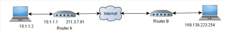
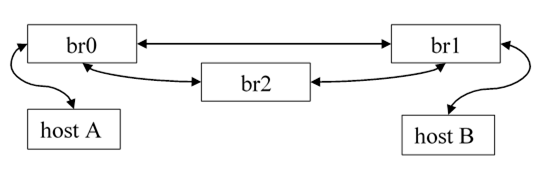
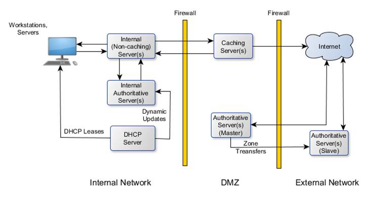